Table of contents
Tapered roller bearings
- Bearing design
- Load carrying capacity
- Compensation of angular misalignments
- Lubrication
- Sealing
- Speeds
- Noise
- Temperature range
- Cages
- Internal clearance
- Dimensions, tolerances
- Suffixes
- Structure of bearing designation
- Dimensioning
- Minimum load
- Design of bearing arrangements
- Mounting and dismounting
- Legal notice regarding data freshness
- Further information
Tapered roller bearings

Tapered roller bearings are particularly suitable where:
- high radial loads occur ➤ section and ➤ section
- high axial loads act on one side ➤ section
- combined loads must be supported (radial and axial forces acting simultaneously) ➤ section
- precise axial guidance of the shaft is required (locating bearing function)
- the bearing arrangement must have very high axial rigidity
- the bearing position is operated clearance-free or under preload (single bearings are adjusted against each other) ➤ section
- high running accuracy is required
- the load carrying capacity of angular contact ball bearings is no longer sufficient and the higher speed suitability of angular contact ball bearings is not required ➤ Figure
- the bearings are not required to compensate misalignments
- the design objective comprises compact, rigid and economical bearing arrangements with a high load carrying capacity
|
Load carrying capacity and speed comparison – single row tapered roller bearings/single row angular contact ball bearings Fr = radial load Cr = basic dynamic load rating nG = limiting speed |
 |
Bearing design
Design variants
Tapered roller bearings are available in an extensive range of single row and multi-row designs. X-life is the new performance standard for tapered roller bearings and stands for eXtended life ➤ link. The key designs based on single row tapered roller bearings are:
- single row tapered roller bearings
- matched tapered roller bearings
- integral tapered roller bearings

Tapered roller bearings are also available in many other designs and sizes, as well as for specific applications, by agreement. For general availability, please contact Schaeffler. An upgrade to X-life performance is available. X-life bearings TPI 241. Matched tapered roller bearings TPI 245. Integral tapered roller bearings TPI 151. Larger catalogue bearings and other bearing designs GL 1.
Available in metric and inch sizes
Tapered roller bearings are produced in metric and inch sizes.
Classification and designation – bearings in metric and inch sizes

Bearings in metric sizes:
- DIN 720 : 2008
- ISO 355 : 2007
- ANSI/ABMA 19 . 1 : 2011 (prefix KJ)
Bearings in inch sizes:
- ANSI/ABMA 19 . 2 : 2013 (prefix K)
Tapered roller bearings of basic design
Fundamental design features
Tapered roller bearings are part of the group of radial roller bearings. In contrast to the ball, the roller has a larger contact area perpendicular to the roller axis. As a result, it can transmit higher forces, has greater rigidity and allows smaller rolling elements under the same load. The single row and multi-row bearings comprise a ribless outer ring, an inner ring with two ribs of different heights and a cage ➤ Figure, ➤ Figure. The cage contains truncated conical rollers. The roller and cage assembly together with the inner ring forms a unit. The low rib retains, in conjunction with the cage, the rollers on the inner ring raceway; the high rib supports the axial force component arising from the tapered form of the rollers. While the tapered rollers roll on the raceways, they slide on the higher rib of the inner ring. The projected lines of contact of the tapered rollers intersect the projected raceways of the inner and outer ring at a point on the bearing axis ➤ Figure. As a result of this geometrical characteristic, tapered roller bearings are highly suitable for supporting combined loads. This also prevents any kinematic forced slippage at the rolling contact.
The high dimensional and geometrical accuracy of the rollers reduces running noise and vibrations
Due to the dimensional and geometrical accuracy of the tapered rollers, the rolling elements in a roller set are subjected to virtually the same proportion of load in the load range. In operation, this leads to low-noise and low-vibration running, as well as a high adjustment accuracy.
|
Single row tapered roller bearing: Fr = radial load Fa = axial load R = roller cone apex α = nominal contact angle |
 |
X-life premium quality

Single row tapered roller bearings are available in numerous series and dimensions as X-life bearings. These bearings exhibit considerably higher performance than comparable tapered roller bearings without X-life characteristics ➤ Figure. This is achieved, in part, by superior ring materials and optimised contact geometry between roller and raceway, as well as between roller and rib. In combination with an increased surface quality, this leads to improved lubricant film formation.
Advantages
Increased customer benefits due to X-life
These technical enhancements offer a range of advantages, such as:
- up to 20 % higher basic dynamic load ratings Cr ➤ Figure
- a higher running accuracy and smooth running
- running with reduced friction and greater energy efficiency (reduction in friction up to 50 %, in the case of tapered roller bearings with a steep taper, up to 75 %)
- lower heat generation in the bearing
- higher limiting speeds
- lower lubricant consumption and therefore longer maintenance intervals if relubrication is carried out
- a measurably longer operating life of the bearings ➤ Figure
- high reliability and operational security
- lower overall operating costs
- compact, environmentally-friendly bearing arrangements.
Lower operating costs, higher machine availability
In conclusion, these advantages improve the overall cost-efficiency of the bearing position significantly and thus bring about a sustainable increase in the efficiency of the machine and equipment.
Suffix XL
X-life tapered roller bearings include the suffix XL in the designation ➤ section.
|
Comparison of basic dynamic load rating Cr of X-life tapered roller bearings with bearings without X-life performance Cr = basic dynamic load rating |
 |
|
Fatigue running time in Weibull diagram – comparison of X-life tapered roller bearings with bearings without X-life performance
|
 |


Areas of application
Due to their special technical features, X-life tapered roller bearings are highly suitable for bearing arrangements in:
- mobile hydraulics (axial piston and orbital motors)
- tractors (wheel bearings and gearboxes)
- vertical mills (grinding rolls)
- hot and cold rolling mills (work rolls in roll stands)
- applications for oil and gas extraction
- offshore and onshore wind turbines (gearboxes)
- construction machinery (road rollers, drill head bearings)

X-life indicates a high product performance density and thus a particularly significant benefit to the customer.
Single row tapered roller bearings
Optimised product characteristics give a sustainable improvement in operating behaviour
Tapered roller bearings are individual, single row bearings of open design which, for technical reasons, are always adjusted against a second tapered roller bearing in a mirror image arrangement ➤ Figure. The bearings are designed such that they reliably cover the extensive demands in relation to generally common requirements. For example, in order to improve the lubricant film formation and running characteristics, the sliding surfaces on the guidance rib of the inner ring, as well as the end faces and contact profile of the rollers, have been optimised ➤ link. In addition, the high production accuracy allows the bearings to be adjusted against each other with high functional security. This in turn leads to improved operating characteristics and thus to a higher operational reliability. Tapered roller bearings are not self-retaining. As a result, the inner ring with the roller and cage assembly can be mounted separately from the outer ring. This gives simplified mounting of the bearings.
|
Single row tapered roller bearing Fr = radial load Fa = axial load α = nominal contact angle |
 |
Matched tapered roller bearings
If the load carrying capacity of a bearing is not sufficient or the shaft is to be guided in both directions with a specific axial clearance, then ready-to‑fit, matched bearing sets are available. Matched tapered roller bearings are essentially available in three arrangements comprising an X, O and tandem arrangement.
|
Matched tapered rolling bearing pairs in tandem, X and O arrangement, load directions, contact lines Fr = radial load Fa = axial load
|
 |


X arrangement
For bearing sets in an X arrangement, the contact lines converge relative to the bearing axis ➤ Figure. Axial forces occur from both directions, but are always only supported by one bearing. The X arrangement is of simple design and the most frequently used arrangement of matched tapered roller bearings fitted in pairs.
O arrangement
For bearing sets in an O arrangement, the contact lines diverge relative to the bearing axis ➤ Figure. Axial forces occur from both directions, but are always only supported by one bearing. The support base is at its largest in the O arrangement, which is beneficial if the component with small bearing spacing must be guided with the smallest possible tilting clearance, or tilting forces must be supported. Bearing arrangements in an O arrangement are relatively rigid and can also support loads resulting from tilting moments.
Tandem arrangement
For bearing sets in a tandem arrangement, the contact lines run parallel to each other. In contrast to an X and O arrangement, the tandem arrangement can only support axial force in one direction. This bearing pair is usually adjusted against another tapered roller bearing, which supports axial forces in the opposite direction.
The product tables ➤ link, contain only a few examples of matched tapered roller bearing sets in an X arrangement for reference purposes. Other matched tapered roller bearing sets are available in an X arrangement by agreement.
Advantages of matched bearing sets
Matched bearing pairs in an O or X arrangement provide an economical solution to various bearing arrangement problems due, for example, to:
- their ability to support high radial loads as well as axial loads in both directions
- the simplified mounting of bearings, as the insertion of fit rings is no longer required and mounting defects are thus avoided
- the precise axial guidance of the shaft; the axial clearance of the bearing pair is already defined in bearing production
- simple lubrication; the lubricant can be easily fed to the rolling system by means of lubrication holes in the fit ring
Ordering and designation system
In order to simplify the ordering process, the ordering designation is modified for matched tapered roller bearings fitted in pairs:
- The first module letter D = 2 (duplex) represents the number of bearings
- The second module letter represents the bearing arrangement:
- B = O arrangement - Back to Back
- F = X arrangement - Face to Face
- T = tandem arrangement
- Where necessary (special design), a third module letter is added as a continuous counter for describing a variant. Example: A, B, … = different set width, variant of intermediate ring design
- The axial internal clearance is indicated explicitly in the designation. For example, A80-120 means that the axial internal clearance of the unmounted bearing pair (delivered condition) is between 80 μm and 120 μm. Ordering example ➤ Figure

The number of bearing pairs must be stated when ordering matched tapered roller bearings.
Integral tapered roller bearings (JK0S) – fitted in pairs
The bearings are predominantly fitted in pairs
Integral tapered roller bearings are ready-to-fit bearing units, which are greased, sealed on one side and predominantly mounted in pairs in an O arrangement ➤ Figure. The bearings are not separable.
There is no need to set the axial internal clearance
The precise axial internal clearance is not achieved by adjusting the bearings, but is set automatically when the recommended bearing seat tolerances are observed. As a result, there is no need to adjust the bearings against each other in the manner normally required. When integral tapered roller bearings are mounted in pairs, a slot is formed on the outer ring for the retaining ring (snap ring BR). Schaeffler integral tapered roller bearings are interchangeable with each other.
When ordering, please always state the number of individual bearings and not the number of bearing pairs. The snap ring must be ordered separately, for example:
- 2 tapered roller bearings JK0S080-A ➤ link
- 1 snap ring BR125
|
Paired integral tapered roller bearing, load directions Fr = radial load Fa = axial load
|
 |
Load carrying capacity
Bearings of basic design
Capable of supporting axial loads in one direction and radial loads
Single row tapered roller bearings can support axial loads in one direction and high radial loads ➤ Figure and ➤ Figure. However, they must always be axially adjusted against a second bearing fitted in a mirror image arrangement. This bearing combination is then fitted in an O or X arrangement.
The larger the contact angle, the higher the axial load carrying capacity
The axial load carrying capacity of the bearings is dependent on the nominal contact angle α ➤ Figure. The greater this angle, the higher the axial load to which the bearing can be subjected. The size of the contact angle – and thus the load carrying capacity of the bearing – is indicated by the value e in the product tables ➤ link. The nominal contact angle α in most bearing series is between 10° and 20°. In special series, α is approximately 28° to 30°. Bearings of series 313, 323..-B, T5ED and T7FC have a very high axial load carrying capacity due to their particularly large contact angle.
Basic load rating and fatigue limit load for bearing pairs comprising single bearings
If two bearings of the same size and design are fitted immediately adjacent to each other in an O or X arrangement, the basic dynamic load rating Cr, the basic static load rating C0r and the fatigue limit load Cur of the bearing pair are as follows:
- Cr = 1,715 · Cr single bearing
- C0r = 2 · C0r single bearing
- Cur = 2 · Cur single bearing
Values for single bearings in the product tables ➤ link.
Matched bearings
Capable of supporting radial loads, axial loads in both directions and moment loads
Matched tapered roller bearings support higher radial forces than single row tapered roller bearings. In X and O arrangements, axial forces and moment loads are supported in both directions. The tandem arrangement can only support axial forces in one direction.
Basic load rating and fatigue limit load for matched bearings
For matched bearing pairs of design DF, the basic load ratings and fatigue limit loads are given in the dimension tables ➤ link.
Integral tapered roller bearings – fitted in pairs
Capable of supporting axial loads in both directions and radial loads
Single row tapered roller bearings fitted in pairs in an O arrangement support high axial loads in both directions and high radial loads ➤ Figure.
Compensation of angular misalignments
Compensation of angular misalignments possible
The modified line contact between the tapered rollers and the raceways ensures optimum stress distribution at the contact points and prevents stress increases at the edges. As a result, the bearings can tolerate certain angular misalignments and give better support of moment loads ➤ Figure.
|
Uniform load distribution due to optimised roller and raceway profile F = load on the roller
|
 |
Permissible angular misalignment
If the load ratio P/C0r ≦ 0,2, the tilting of the bearing rings relative to each other must not exceed 4 angular minutes. This is, however, subject to the position of the shaft and housing axis remaining constant (no dynamic movements).
If larger loads/misalignments or dynamic angular defects are present, please consult Schaeffler.
Lubrication
Single row and matched tapered roller bearings
Oil or grease lubrication is possible
Single row and matched tapered roller bearings are not greased. These bearings must be lubricated with oil or grease.
Compatibility with plastic cages
When using bearings with plastic cages, compatibility between the lubricant and the cage material must be ensured if synthetic oils, lubricating greases with a synthetic oil base or lubricants containing a high proportion of EP additives are used.
Observe oil change intervals
Aged oil and additives in the oil can impair the operating life of plastics at high temperatures. As a result, stipulated oil change intervals must be strictly observed.
Integral tapered roller bearings
Usually maintenance-free due to initial greasing
Integral tapered roller bearings are supplied already greased with a quality grease to DIN 51825. The grease filling is measured such that these bearings are maintenance-free during their operating lives in most applications.
Sealing
Single row and matched tapered roller bearings
Provide seals in the adjacent construction
Single row and matched tapered roller bearings are not sealed, i. e. sealing of the bearing position must be carried out in the adjacent construction. This must reliably prevent:
- moisture and contaminants from entering the bearing
- the egress of lubricant from the bearing position
Integral tapered roller bearings
Integral tapered roller bearings are sealed on one side with a contact seal (lip seal).
Speeds
Limiting speeds and reference speeds in the product tables
The product tables give two speeds for most bearings:
- the kinematic limiting speed nG
- the thermal speed rating nϑr
Limiting speeds
The limiting speed nG is the kinematically permissible speed of the bearing. Even under favourable mounting and operating conditions, this value should not be exceeded without prior consultation with Schaeffler ➤ link.
Reference speeds
nϑr is used to calculate nϑ
The thermal speed rating nϑr is not an application-oriented speed limit, but is a calculated ancillary value for determining the thermally safe operating speed nϑ ➤ link.
Bearings with contact seals
For bearings with contact seals, no speed ratings are defined in accordance with DIN ISO 15312:2004. As a result, only the limiting speed nG is given in the product tables for these bearings.
Speeds for matched bearings fitted in pairs
Observing the thermal balance
For matched bearing pairs, the limiting speeds nG given in the product tables are permissible if the less favourable thermal balance of the bearing pair is taken into consideration in the operating conditions.
Noise
The Schaeffler Noise Index (SGI) has been developed as a new feature for comparing the noise level of different bearing types and series. As a result, a noise evaluation of rolling bearings can now be carried out for the first time.
Schaeffler Noise Index
The SGI value is based on the maximum permissible noise level of a bearing in accordance with internal standards, which is calculated on the basis of ISO 15242. In order that different bearing types and series can be compared, the SGI value is plotted against the basic static load rating C0.
This permits direct comparisons between bearings with the same load carrying capacity. The upper limit value is given in each of the diagrams. This means that the average noise level of the bearings is lower than illustrated in the diagram.
The Schaeffler Noise Index is an additional performance characteristic in the selection of bearings for noise-sensitive applications. The specific suitability of a bearing for an application in terms of installation space, load carrying capacity or speed limit for example, must be checked independently of this.
|
Schaeffler Noise Index SGI = Schaeffler Noise Index C0 = basic static load rating |
 |
Temperature range
Limiting values
The operating temperature of the bearings is limited by:
- the dimensional stability of the bearing rings and tapered rollers
- the cage
- the lubricant
- the seals
Possible operating temperatures of tapered roller bearings ➤ Table.
Permissible temperature ranges
|
Operating temperature |
Open tapered roller bearings |
Sealed tapered |
|
|---|---|---|---|
|
|
D ≦ 220 mm, |
D > 220 mm, |
–30 °C to +110 °C, |

In the event of anticipated temperatures which lie outside the stated values, please contact Schaeffler.
Cages
Sheet steel cages are used as standard
Open tapered roller bearings have sheet steel cages. Plastic cages are available by agreement.
Cages for JK0S
Integral tapered roller bearings have cages made from glass fibre reinforced polyamide PA66.
For high continuous temperatures and applications with difficult operating conditions, bearings with sheet steel cages should be used. If there is any uncertainty regarding cage suitability, please consult Schaeffler.
Internal clearance
For tapered roller bearings, the axial internal clearance sa is a characteristic value. This is the result of mounting the bearing against a second tapered roller bearing ➤ Figure.|
Axial internal clearance sa = axial internal clearance |
 |
Indicating the axial internal clearance
The axial internal clearance is indicated explicitly in the designation. Ordering example ➤ Figure.
Matched tapered roller bearing sets
Simple mounting of the bearing sets in the mounting position is achieved by precise matching of the intermediate ring to the required geometric axial internal clearance. As a result, ready-to-fit, matched bearing sets are made available by Schaeffler. This offers high economical and technical advantages such as:
- Uncomplicated mounting: mounting defects are, for example, avoided by the intermediate ring, which is supplied already matched.
- Knowledge and inclusion of the axial deflection of the bearings, as well as highly developed measurement methods, guarantee a precise design of the axial internal clearance. This ensures precise axial guidance of the shaft
- Simple maintenance and high operational reliability are achieved by means of design elements, lubrication grooves and holes in the intermediate ring
Dimensions, tolerances
Dimension standards – bearings in metric sizes
The main dimensions of bearings in metric sizes correspond to ISO 355:2007 and DIN 720:2008. Bearings in metric sizes with the prefix KJ correspond to ANSI/ABMA 19.1:2011.
Chamfer dimensions
Tapered roller bearings in metric sizes
The limiting dimensions for the chamfer dimensions of metric tapered roller bearings to DIN/ISO correspond to ISO 582:1995. Overview and limiting values for metric tapered roller bearings to DIN/ISO ➤ link.
Minimum chamfer dimensions for metric tapered roller bearings to ANSI/ABMA with the prefix KJ correspond to ANSI/ABMA 19.1:2011. The values are given in the product tables.
Bearings in inch sizes to ANSI/ABMA
Minimum chamfer dimensions rmin for bearings in inch sizes correspond to ANSI/ABMA 19.2:2013. The values are given in the product tables ➤ link.
Tolerances
All tapered roller bearings to DIN 720, ISO 355 and integral tapered roller bearings have the tolerance class Normal to ISO 492:2014. In contrast to the standard, X-life bearings achieve improved radial runout values tKia and tKea, in addition to dedicated axial runout values tSia ➤ Figure. Inner ring tolerances ➤ Table, outer ring tolerances ➤ Table, width tolerances ➤ Table. This excludes bearings of series 320, 329, 330, 331, 332 where d ≦ 200 mm: These have the tolerance class 6X ➤ link. The width tolerances tΔTs of the T7FC series with the suffix XL correspond to the tolerance class 6X in accordance with ISO 492:2014 ➤ link.
Inner ring tolerances, tolerance class Normal
|
Nominal |
Bore |
Variation |
Radial runout |
Axial runout |
||||
|---|---|---|---|---|---|---|---|---|
|
ISO 492 |
X-life |
X-life |
||||||
|
d |
tΔdmp |
tVdsp |
tVdmp |
tKia |
tKia |
tSia |
||
|
mm |
μm |
μm |
μm |
μm |
μm |
μm |
||
|
over |
incl. |
U |
L |
max. |
max. |
max. |
max. |
max. |
|
10 |
18 |
0 |
–12 |
12 |
9 |
15 |
7 |
10 |
|
18 |
30 |
0 |
–12 |
12 |
9 |
18 |
8 |
13 |
|
30 |
50 |
0 |
–12 |
12 |
9 |
20 |
9 |
13 |
|
50 |
80 |
0 |
–15 |
15 |
11 |
25 |
10 |
15 |
|
80 |
120 |
0 |
–20 |
20 |
15 |
30 |
13 |
18 |
|
120 |
180 |
0 |
–25 |
25 |
19 |
35 |
19 |
20 |
|
180 |
250 |
0 |
–30 |
30 |
23 |
50 |
24 |
25 |
|
250 |
315 |
0 |
–35 |
35 |
26 |
60 |
28 |
28 |
|
315 |
400 |
0 |
–40 |
40 |
30 |
70 |
33 |
35 |
Tolerance symbols ➤ Table
U = upper limit deviation
L = lower limit deviation
tSia = axial runout to Schaeffler standard ➤ Figure
Outer ring tolerances, tolerance class Normal
|
Nominal |
Deviation |
Variation |
Radial runout |
||||
|---|---|---|---|---|---|---|---|
|
ISO 492 |
X-life |
||||||
|
D |
tΔDmp |
tVDsp |
tVDmp |
tKea |
tKea |
||
|
mm |
μm |
μm |
μm |
μm |
μm |
||
|
over |
incl. |
U |
L |
max. |
max. |
max. |
max. |
|
18 |
30 |
0 |
–12 |
12 |
9 |
18 |
9 |
|
30 |
50 |
0 |
–14 |
14 |
11 |
20 |
10 |
|
50 |
80 |
0 |
–16 |
16 |
12 |
25 |
13 |
|
80 |
120 |
0 |
–18 |
18 |
14 |
35 |
16 |
|
120 |
150 |
0 |
–20 |
20 |
15 |
40 |
19 |
|
150 |
180 |
0 |
–25 |
25 |
19 |
45 |
21 |
|
180 |
250 |
0 |
–30 |
30 |
23 |
50 |
25 |
|
250 |
315 |
0 |
–35 |
35 |
26 |
60 |
30 |
|
315 |
400 |
0 |
–40 |
40 |
30 |
70 |
34 |
|
400 |
500 |
0 |
–45 |
45 |
34 |
80 |
40 |
|
500 |
630 |
0 |
–50 |
60 |
38 |
100 |
46 |
Tolerance symbols ➤ Table
U = upper limit deviation
L = lower limit deviation
Width tolerances, tolerance class Normal
|
Nominal |
Deviation of |
Deviation of |
Width deviation |
||||||||
|---|---|---|---|---|---|---|---|---|---|---|---|
|
d |
tΔBs |
tΔCs |
tΔTs |
tΔT1s |
tΔT2s |
||||||
|
mm |
μm |
μm |
μm |
μm |
μm |
||||||
|
over |
incl. |
U |
L |
U |
L |
U |
L |
U |
L |
U |
L |
|
10 |
18 |
0 |
–120 |
0 |
–120 |
+200 |
0 |
+100 |
0 |
+100 |
0 |
|
18 |
30 |
0 |
–120 |
0 |
–120 |
+200 |
0 |
+100 |
0 |
+100 |
0 |
|
30 |
50 |
0 |
–120 |
0 |
–120 |
+200 |
0 |
+100 |
0 |
+100 |
0 |
|
50 |
80 |
0 |
–150 |
0 |
–150 |
+200 |
0 |
+100 |
0 |
+100 |
0 |
|
80 |
120 |
0 |
–200 |
0 |
–200 |
+200 |
–200 |
+100 |
–100 |
+100 |
–100 |
|
120 |
180 |
0 |
–250 |
0 |
–250 |
+350 |
–250 |
+150 |
–150 |
+200 |
–100 |
|
180 |
250 |
0 |
–300 |
0 |
–300 |
+350 |
–250 |
+150 |
–150 |
+200 |
–100 |
|
250 |
315 |
0 |
–350 |
0 |
–350 |
+350 |
–250 |
+150 |
–150 |
+200 |
–100 |
|
315 |
400 |
0 |
–400 |
0 |
–400 |
+400 |
–400 |
+200 |
–200 |
+200 |
–200 |
Tolerance symbols ➤ Table
U = upper limit deviation
L = lower limit deviation
|
Axial and radial runout on the drawing D = outside diameter d = bearing bore |
 |
Series 320, 329, 330, 331, 332 for d ≦ 200 mm and bearings with the prefix KJ
Bearings 320, 329, 330, 331, 332 for d ≦ 200 mm and bearings with the prefix KJ have dimensional and running tolerances to the tolerance class Normal, but have restricted width tolerances to tolerance class 6X in accordance with ISO 492:2014 ➤ Table; inner ring tolerances ➤ Table, outer ring tolerances ➤ Table.
Width tolerances, tolerance class 6X
|
Nominal |
Deviation |
Deviation |
Width deviation |
||||||||
|---|---|---|---|---|---|---|---|---|---|---|---|
|
d |
tΔBs |
tΔCs |
tΔTs |
tΔT1s |
tΔT2s |
||||||
|
mm |
μm |
μm |
μm |
μm |
μm |
||||||
|
over |
incl. |
U |
L |
U |
L |
U |
L |
U |
L |
U |
L |
| 10 | 18 | 0 | –50 | 0 | –100 | +100 | 0 | +50 | 0 | +50 | 0 |
| 18 | 30 | 0 | –50 | 0 | –100 | +100 | 0 | +50 | 0 | +50 | 0 |
| 30 | 50 | 0 | –50 | 0 | –100 | +100 | 0 | +50 | 0 | +50 | 0 |
| 50 | 80 | 0 | –50 | 0 | –100 | +100 | 0 | +50 | 0 | +50 | 0 |
| 80 | 120 | 0 | –50 | 0 | –100 | +100 | 0 | +50 | 0 | +50 | 0 |
| 120 | 180 | 0 | –50 | 0 | –100 | +150 | 0 | +50 | 0 | +100 | 0 |
| 180 | 200 | 0 | –50 | 0 | –100 | +150 | 0 | +50 | 0 | +100 | 0 |
Tolerance symbols ➤ Table
U = upper limit deviation
L = lower limit deviation
Restricted tolerances to tolerance class 5
Tapered roller bearings are also available by agreement with restricted tolerances to tolerance class 5 in accordance with ISO 492:2014; inner ring tolerances ➤ Table, outer ring tolerances ➤ Table, width tolerances ➤ Table.
Restricted inner ring tolerances, tolerance class 5
|
Nominal |
Bore |
Variation |
Radial |
Axial runout of |
|||
|---|---|---|---|---|---|---|---|
|
d |
tΔdmp |
tVdsp |
tVdmp |
tKia |
tSd |
||
|
mm |
μm |
μm |
μm |
μm |
μm |
||
|
over |
incl. |
U |
L |
max. |
max. |
max. |
max. |
|
10 |
18 |
0 |
–7 |
5 |
5 |
5 |
7 |
|
18 |
30 |
0 |
–8 |
6 |
5 |
5 |
8 |
|
30 |
50 |
0 |
–10 |
8 |
5 |
6 |
8 |
|
50 |
80 |
0 |
–12 |
9 |
6 |
7 |
8 |
|
80 |
120 |
0 |
–15 |
11 |
8 |
8 |
9 |
|
120 |
180 |
0 |
–18 |
14 |
9 |
11 |
10 |
|
180 |
250 |
0 |
–22 |
17 |
11 |
13 |
11 |
|
250 |
315 |
0 |
–25 |
19 |
13 |
13 |
13 |
|
315 |
400 |
0 |
–30 |
23 |
15 |
15 |
15 |
Tolerance symbols ➤ Table
U = upper limit deviation
L = lower limit deviation
Restricted outer ring tolerances, tolerance class 5
|
Nominal |
Deviation of |
Variation |
Radial |
Axial runout of |
|||
|---|---|---|---|---|---|---|---|
|
D |
tΔDmp |
tVDsp |
tVDmp |
tKea |
tSi |
||
|
mm |
μm |
μm |
μm |
μm |
μm |
||
|
over |
incl. |
U |
L |
max. |
max. |
max. |
max. |
|
18 |
30 |
0 |
–8 |
6 |
5 |
6 |
4 |
|
30 |
50 |
0 |
–9 |
7 |
5 |
7 |
4 |
|
50 |
80 |
0 |
–11 |
8 |
6 |
8 |
4 |
|
80 |
120 |
0 |
–13 |
10 |
7 |
10 |
4,5 |
|
120 |
150 |
0 |
–15 |
11 |
8 |
11 |
5 |
|
150 |
180 |
0 |
–18 |
14 |
9 |
13 |
5 |
|
180 |
250 |
0 |
–20 |
15 |
10 |
15 |
5,5 |
|
250 |
315 |
0 |
–25 |
19 |
13 |
18 |
6,5 |
|
315 |
400 |
0 |
–28 |
22 |
14 |
20 |
6,5 |
|
400 |
500 |
0 |
–33 |
26 |
17 |
24 |
8,5 |
|
500 |
630 |
0 |
–38 |
30 |
20 |
30 |
10 |
Tolerance symbols ➤ Table
U = upper limit deviation
L = lower limit deviation
Width tolerances, tolerance class 5
|
Nominal |
Deviation of |
Deviation of |
Width deviation |
||||||||
|---|---|---|---|---|---|---|---|---|---|---|---|
|
d |
tΔBs |
tΔCs |
tΔTs |
tΔT1s |
tΔT2s |
||||||
|
mm |
μm |
μm |
μm |
μm |
μm |
||||||
|
over |
incl. |
U |
L |
U |
L |
U |
L |
U |
L |
U |
L |
|
10 |
18 |
0 |
–200 |
0 |
–200 |
+200 |
–200 |
+100 |
–100 |
+100 |
–100 |
|
18 |
30 |
0 |
–200 |
0 |
–200 |
+200 |
–200 |
+100 |
–100 |
+100 |
–100 |
|
30 |
50 |
0 |
–240 |
0 |
–240 |
+200 |
–200 |
+100 |
–100 |
+100 |
–100 |
|
50 |
80 |
0 |
–300 |
0 |
–300 |
+200 |
–200 |
+100 |
–100 |
+100 |
–100 |
|
80 |
120 |
0 |
–400 |
0 |
–400 |
+200 |
–200 |
+100 |
–100 |
+100 |
–100 |
|
120 |
180 |
0 |
–500 |
0 |
–500 |
+350 |
–250 |
+150 |
–150 |
+200 |
–100 |
|
180 |
250 |
0 |
–600 |
0 |
–600 |
+350 |
–250 |
+150 |
–150 |
+200 |
–100 |
|
250 |
315 |
0 |
–700 |
0 |
–700 |
+350 |
–250 |
+150 |
–150 |
+200 |
–100 |
|
315 |
400 |
0 |
–800 |
0 |
–800 |
+400 |
–400 |
+200 |
–200 |
+200 |
–200 |
Tolerance symbols ➤ Table
U = upper limit deviation
L = lower limit deviation
Total width tolerance of matched bearings
The tolerance for the total width 2T of matched bearing sets of design DF is determined from the axial internal clearance and the deviations of the width tΔTs of the single bearings. The tolerance for the total width 2B is determined from the inner ring width tΔBs of the single bearings ➤ Table.
Bearings in inch sizes to ANSI/ABMA
Tapered roller bearings with the prefix K are manufactured as standard to the following tables. The values in the tables meet the requirements for normal tolerances in accordance with ANSI/ABMA 19.2:2013 and, in some cases, exceed these by a considerable margin. Exception: bearings with the prefix KJ correspond to ISO 492:2014. The bore and outside diameters of bearings in inch sizes have plus tolerances; inner ring tolerances ➤ Table, outer ring tolerances ➤ Table, width tolerances ➤ Table.
Inner ring tolerances, bearings in inch sizes
|
Nominal |
Bore deviation |
Radial runout |
Axial runout |
|||
|---|---|---|---|---|---|---|
|
According |
X-life |
X-life |
||||
|
d |
tΔdmp |
tKia |
tKia |
tSia |
||
|
mm |
μm |
μm |
μm |
μm |
||
|
over |
incl. |
U |
L |
max. |
max. |
max. |
|
10 |
18 |
+12 |
0 |
15 |
7 |
10 |
|
18 |
30 |
+12 |
0 |
18 |
8 |
13 |
|
30 |
50 |
+12 |
0 |
20 |
9 |
13 |
|
50 |
80 |
+12 |
0 |
25 |
10 |
15 |
|
80 |
120 |
+25 |
0 |
30 |
13 |
18 |
|
120 |
180 |
+25 |
0 |
35 |
19 |
20 |
|
180 |
250 |
+25 |
0 |
50 |
24 |
25 |
|
250 |
304,8 |
+25 |
0 |
50 |
28 |
28 |
|
304,8 |
315 |
+50 |
0 |
50 |
28 |
28 |
|
315 |
400 |
+50 |
0 |
50 |
33 |
35 |
|
400 |
500 |
+50 |
0 |
50 |
39 |
38 |
|
500 |
609,6 |
+50 |
0 |
50 |
45 |
43 |
|
609,6 |
800 |
+75 |
0 |
75 |
54 |
‒ |
Tolerance symbols ➤ Table
U = upper limit deviation
L = lower limit deviation
tSia = axial runout to Schaeffler standard ➤ Figure
Outer ring tolerances, bearings in inch sizes
|
Nominal |
Bore |
Radial runout |
|||
|---|---|---|---|---|---|
|
According |
X-life |
||||
|
D |
tΔDmp |
tKea |
tKea |
||
|
mm |
μm |
μm |
μm |
||
|
over |
incl. |
U |
L |
max. |
max. |
|
18 |
30 |
+25 |
0 |
18 |
9 |
|
30 |
50 |
+25 |
0 |
20 |
10 |
|
50 |
80 |
+25 |
0 |
25 |
13 |
|
80 |
120 |
+25 |
0 |
35 |
16 |
|
120 |
150 |
+25 |
0 |
40 |
19 |
|
150 |
180 |
+25 |
0 |
45 |
21 |
|
180 |
250 |
+25 |
0 |
50 |
25 |
|
250 |
304,8 |
+25 |
0 |
50 |
29 |
|
304,8 |
609,6 |
+50 |
0 |
50 |
45 |
|
609,6 |
800 |
+75 |
0 |
75 |
54 |
Tolerance symbols ➤ Table
U = upper limit deviation
L = lower limit deviation
Width tolerances, bearings in inch sizes
|
Nominal |
Deviation of |
Deviation of |
Width deviation |
||||
|---|---|---|---|---|---|---|---|
|
d |
tΔBs |
tΔCs |
tΔTs |
||||
|
mm |
μm |
μm |
μm |
||||
|
over |
incl. |
U |
L |
U |
L |
U |
L |
|
10 |
50 |
0 |
–120 |
0 |
–120 |
+200 |
0 |
|
50 |
80 |
0 |
–150 |
0 |
–150 |
+200 |
0 |
|
80 |
101,6 |
0 |
–200 |
0 |
–200 |
+200 |
0 |
|
101,6 |
120 |
0 |
–200 |
0 |
–200 |
+350 |
–250 |
|
120 |
180 |
0 |
–250 |
0 |
–250 |
+350 |
–250 |
|
180 |
304,8 |
0 |
–250 |
0 |
–250 |
+350 |
–250 |
|
304,8 |
800 |
0 |
–250 |
0 |
–250 |
+375 |
–375 |
Tolerance symbols ➤ Table
U = upper limit deviation
L = lower limit deviation
Suffixes
For a description of the suffixes used in this chapter ➤ Table and medias interchange http://www.schaeffler.de/std/1B69.
Suffixes and corresponding descriptions
|
Suffix |
Description of suffix |
|---|---|
|
A |
Modified internal construction (excluding bearings to ANSI/ABMA) |
|
B |
Increased contact angle (for bearings to DIN) |
|
DF-A..-.. |
Two tapered roller bearings matched in an X arrangement, |
|
X |
External dimensions matched to international standards |
|
XL |
X-life |
Tapered roller bearings for special applications
Special tapered roller bearings are available for applications where tapered roller bearing arrangements are used under very difficult operating conditions, for example at high operating temperatures or with heavily contaminated lubricating oil. In such cases, please consult Schaeffler. Suffixes for special designs ➤ Table.
Special designs, available by agreement
|
Suffix |
Description of suffix |
|---|---|
|
DB-A..-.. |
Two tapered roller bearings matched in an O arrangement, with an intermediate ring between the outer rings and the inner rings, axial internal clearance between .. and .. in μm |
|
DT |
Two tapered roller bearings matched in a tandem arrangement, with an intermediate ring between the outer rings |
|
P5 |
Bearing in tolerance class 5 |
Other special designs with suffixes are available by agreement, such as for:
- dimensional stabilisation
- special heat treatment
- special materials
- tapered roller bearings with reduced friction
- tolerance classes
- restricted width tolerances
Structure of bearing designation
Examples of composition of bearing designation
The designation of bearings follows a set model. Examples ➤ Figure to ➤ Figure. For the formation of designations see DIN 623-1:1993 ➤ link, DIN 720:2008 ➤ link, ISO 10317:2008, ISO 355:2007 ➤ link, ANSI/ABMA 19.1:2011 and ANSI/ABMA 19.2:2013.
|
Single row tapered roller bearing, |
 |
|
Single row tapered roller bearing, |
 |
|
Single row tapered roller bearing, |
 |
|
Matched tapered roller bearing pair: designation structure |
 |
|
Integral tapered roller bearing: designation structure |
 |
Dimensioning
Equivalent dynamic bearing load
P = Fr under purely radial load of constant magnitude and direction
The basic rating life equation L = (Cr/P)p used in the dimensioning of radial bearings under dynamic load assumes a radial load P of constant magnitude. If the bearing is subjected to purely radial load, the radial load Fr is used directly in the rating life equation for P (P = Fr).
P is a substitute force for combined load
If this condition is not met, a constant radial force must first be determined for the rating life calculation that (in relation to the rating life) represents an equivalent load. This force is known as the equivalent dynamic load P.
Fa/Fr ≦ e or Fa/Fr > e
The calculation of P is dependent on the load ratio Fa/Fr and the factor e.
Single bearings and JK0S bearings
For single bearings under dynamic load and integral tapered roller bearings ➤ Equation and ➤ Equation.
Equivalent dynamic load
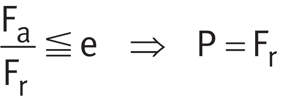
Equivalent dynamic load
Legend
| P | N |
Equivalent dynamic bearing load |
| Fr | N |
Radial load |
| Fa | N |
Resulting axial force ➤ Table. |
| e, Y | - |
Factors ➤ dimension table |
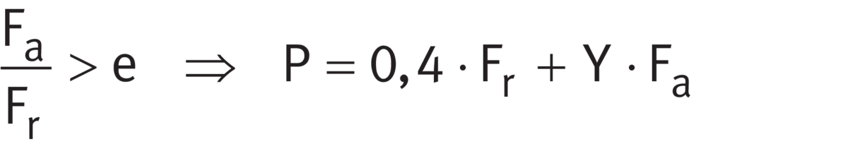
Bearing pairs in O or X arrangement
For bearing pairs under dynamic load in an O or X arrangement comprising single bearings ➤ Equation and ➤ Equation.
Equivalent dynamic load

Equivalent dynamic load
Legend
| P | N |
Equivalent dynamic bearing load |
| Fr | N |
Radial load |
| Fa | N |
Resulting axial force ➤ Table. |
| e, Y | - |
Factors ➤ link |
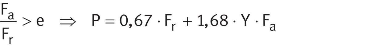
Matched bearing pairs
For matched bearing pairs under dynamic load 313 (320, 322, 329)..-DF-A ➤ Equation and ➤ Equation.
Equivalent dynamic load

Equivalent dynamic load
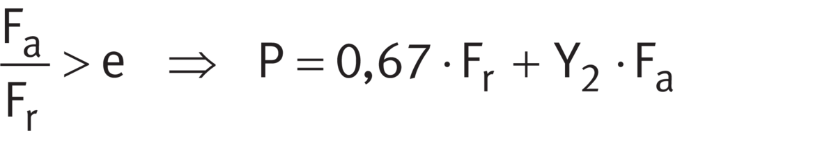
Legend
| P | N |
Equivalent dynamic bearing load |
| Fr | N |
Radial load |
| Fa | N |
Resulting axial force. |
| e, Y1, Y2 | - |
Factors ➤ link |
Calculation of internal resulting axial force Fa for single bearings and for bearing pairs in an X and O arrangement
Reasons why the internal resulting axial force Fa must be taken into consideration
Single row tapered roller bearings transmit radial forces from one raceway to the other oblique to the bearing axis. In the case of a shaft supported by two single row tapered roller bearings of identical or different size, the radial load on bearing A leads, due to the inclination of the raceways (α0 ≠ 0°), to an axial load on bearing B. The radial load on bearing B also has the effect of an axial load on bearing A; external forces in bearing systems of this type ➤ Figure and ➤ Figure. This internal resulting axial force Fa must be taken into consideration in the calculation of the equivalent dynamic bearing load P.
Equations for calculation
Equations for calculation of resulting axial force Fa ➤ Table.
Preconditions for calculation
Bearing A is subjected to a radial load FrA, bearing B to a radial load FrB ➤ Figure and ➤ Figure. FrA and FrB act at the central pressure points of the bearings and are always regarded as positive. The bearings are clearance-free, but without preload.
The stated equations for determining the axial load correspond to an approximation carried out under the assumption of a load zone of 180° in bearings under radial load. For a more precise calculation, the use of BEARINX or BEARINX-online is recommended.
Equations for calculation of the internal resulting axial force Fa
|
Case |
Load ratio |
External axial force |
|---|---|---|
|
1 |
|
Ka ≧ 0 |
| 2 |  |
|
| 3 | |
|
|
continued ▼ |
||


Parameters ➤ Equation, ➤ Figure and ➤ Figure
YA = YB ➤ link
Equations for calculation of the internal resulting axial force Fa
|
Case |
Load ratio |
Resulting axial force Fa |
|
|---|---|---|---|
|
Bearing A |
Bearing B |
||
|
1 |
|
|
Fa is not taken into consideration in the calculation |
| 2 | |
|
Fa is not taken into consideration in the calculation |
| 3 | |
Fa is not taken into consideration in the calculation |
|
|
continued ▲ |
|||


Parameters ➤ Equation, ➤ Figure and ➤ Figure
YA = YB ➤ link
|
Adjusted bearing arrangement with two single row tapered roller bearings in O arrangement, external forces Ka = external axial force acting on the shaft FrA = radial load, bearing A FrB = radial load, bearing B |
 |
|
Adjusted bearing arrangement with two single row tapered roller bearings in X arrangement, external forces Ka = external axial force acting on the shaft FrA = radial load, bearing A FrB = radial load, bearing B |
 |
Example of calculation of internal resulting axial force Fa
Bearing arrangement for pinion shaft
Two single row tapered roller bearings are used for the bearing arrangement of a pinion shaft ➤ Figure. The bearing arrangement should be adjusted and in an O arrangement. In order to calculate the basic rating life of bearing A, the equivalent dynamic bearing load PA must be determined.
|
BEARINX calculation model: load on bearing A and B Ka = external axial force = 6,52 kN Kr = external radial force Kt = tangential force FrA = radial load, bearing A (resultant of reaction forces FyA and FzA ) FrB = radial load, bearing B (resultant of reaction forces FyB and FzB ) l1 = spacing between pinion and contact cone apex of bearing A l2 = spacing between contact cone apexes of bearing A and bearing B |
 |
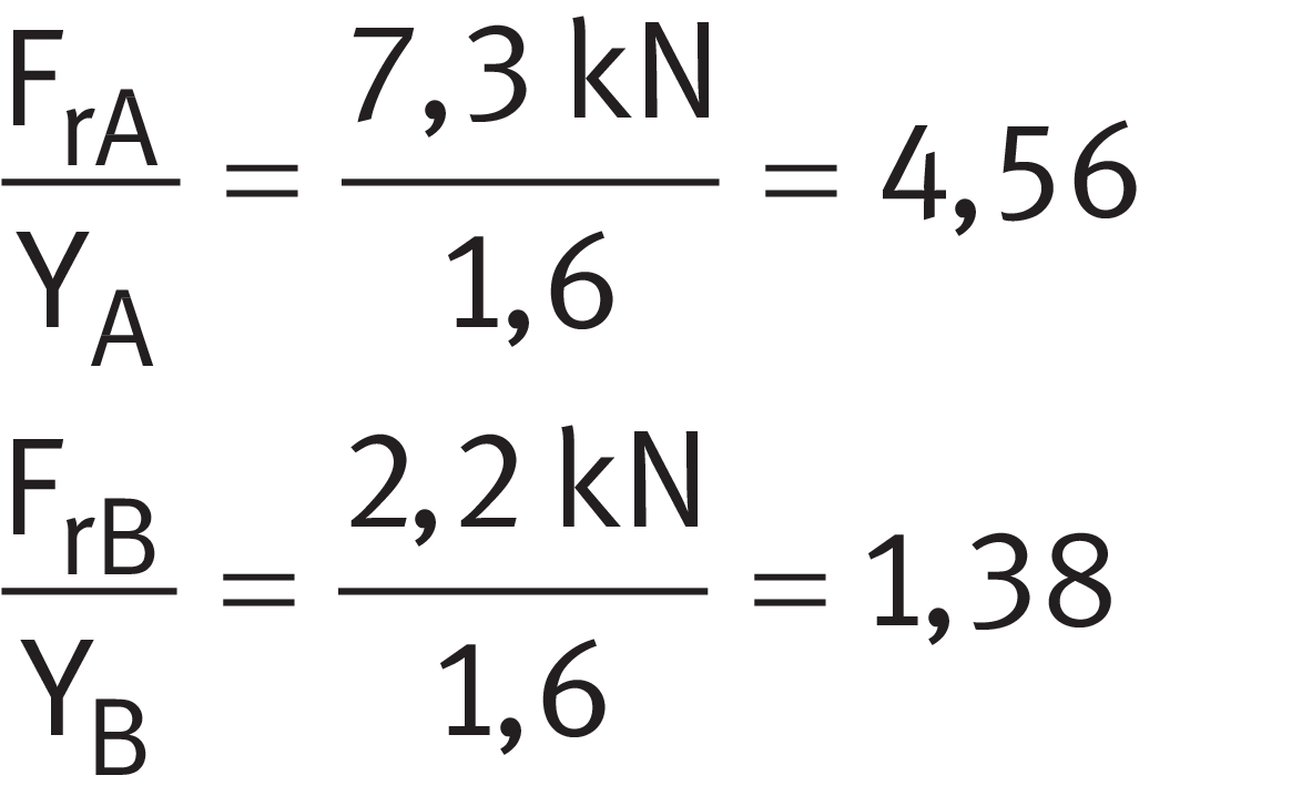
The resulting radial forces FrA and FrB on the bearings must be determined from the external radial force Kr and the tangential force Kt by the solution of the equilibrium of moments and forces on the shaft. Result:
- FrA = 7,3 kN
- FrB = 2,2 kN
In a bearing arrangement with two single bearings, the resulting axial force Fa must be taken into consideration
Since this is an adjusted bearing arrangement with two single bearings, the internal resulting axial force Fa in the bearing system must be taken into consideration in the bearing calculation in accordance with ➤ Table. For both tapered roller bearings YA = YB = 1,6. Loads ➤ Figure. Tapered roller bearing 32206-XL is envisaged for bearing A.
Step 1
Calculate the load ratio using ➤ Equation.
Load ratio
Step 2
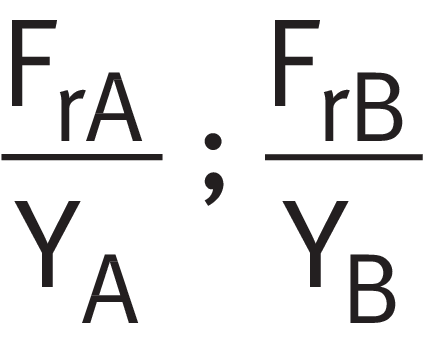
Compare the result with possible cases ➤ Table. Case 2 or case 3 can be considered ➤ Table.
Equations for calculation of the internal resulting axial force Fa
|
Case |
Load ratio |
External axial force |
Resulting axial force Fa |
|
|---|---|---|---|---|
|
Bearing A |
Bearing B |
|||
| 2 | |
|
|
‒ |
| 3 | |
|
‒ |
|

Parameters ➤ Equation
YA = YB = 1,6
Step 3
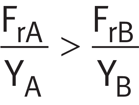
Using ➤ Equation, check whether case 2 applies ➤ Table.
External axial force in relation to load ratio
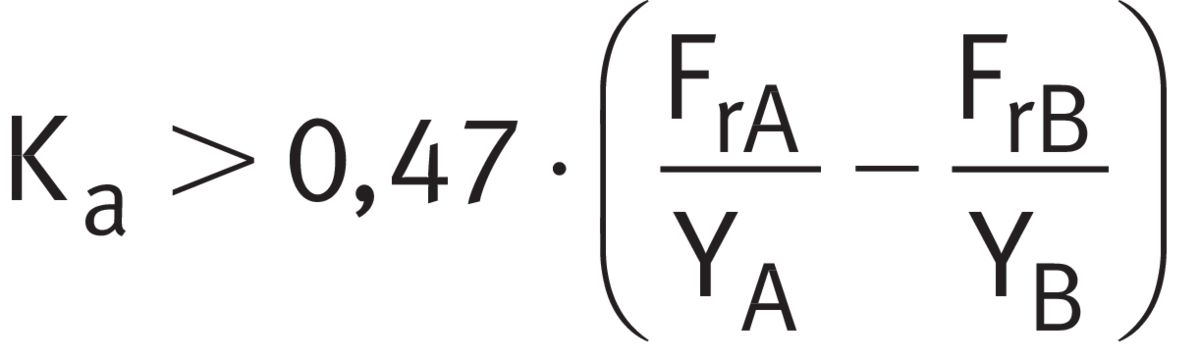

If case 2 applies ➤ Table. This means that bearing A supports the external axial force Ka.
Step 4
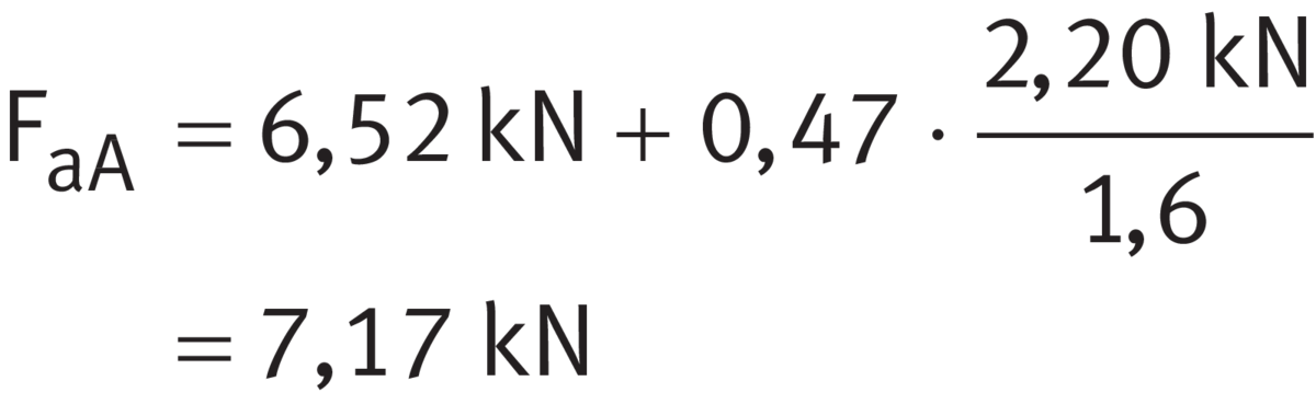
Calculating Fa
Using ➤ Equation, calculate the internal resulting axial force Fa for bearing A. The calculations are in accordance with ➤ Table, case 2.
Internal resulting axial force for bearing A
Example of calculation of P
Using value Fa in the calculation of P
Using ➤ Equation, calculate the ratio between the axial force Fa and radial force Fr of bearing A and compare this with the limit value e in accordance with the product table (in this instance e = 0,37).
Load ratio, bearing A

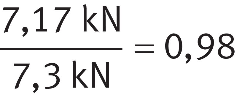
This gives:
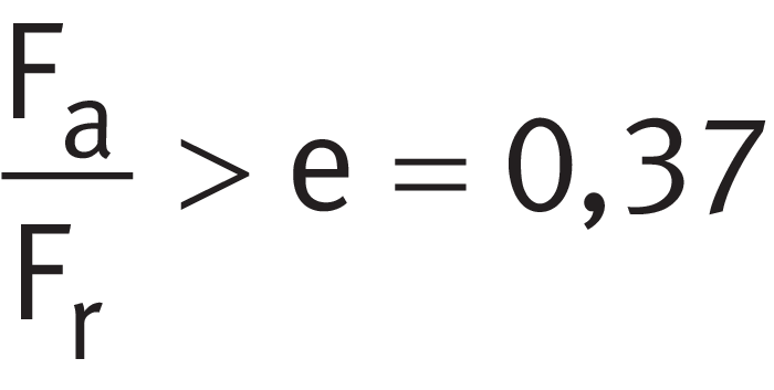
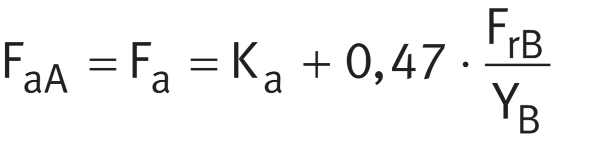
As a result, the axial force Fa of bearing A (FaA) must be taken into consideration within the equivalent bearing load PA of bearing A ➤ Equation and thus ➤ Equation applies.
P for Fa/Fr > e


The equivalent dynamic bearing load PA of bearing A is then used to calculate the basic rating life of bearing A.
Equivalent static bearing load
Single bearings and JK0S bearings
For single bearings under static load and integral tapered roller bearings ➤ Equation and ➤ Equation.
Equivalent static load
Equivalent static load

Legend
| P0 | N |
Equivalent static bearing load |
| F0r, F0a | N |
Largest radial or axial load present (maximum load) |
| Y0 | - |
Axial load factor |
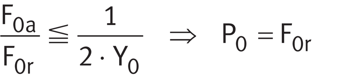
For bearing pairs under static load in an O or X arrangement ➤ Equation.
Equivalent static load

Legend
| P0 | N |
Equivalent static bearing load |
| F0r, F0a | N |
Largest radial or axial load present (maximum load) |
| Y0 | - |
Axial load factor |
For matched bearing pairs under static load 313 (320, 322, 329)..-DF-A.. ➤ Equation.
Equivalent static load

Legend
| P0 | N |
Equivalent static bearing load |
| F0r, F0a | N |
Largest radial or axial load present (maximum load) |
| Y0 | - |
Axial load factor |
Static load safety factor
S0 = C0/P0
In addition to the basic rating life L (L10h), it is also always necessary to check the static load safety factor S0 ➤ Equation.
Static load safety factor
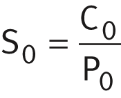
Legend
| S0 | - |
Static load safety factor |
| C0 | N |
Basic static load rating |
| P0 | N |
Equivalent static bearing load |
Minimum load
In order to prevent damage due to slippage, a minimum radial load of P > C0r/60 is required
In order that no slippage occurs between the contact partners, the tapered roller bearings must be constantly subjected to a sufficiently high load. Based on experience, a minimum radial load of the order of P > C0r/60 is thus necessary. In most cases, however, the radial load is already higher than the requisite minimum load due to the weight of the supported parts and the external forces.
If the minimum radial load is lower than indicated above, please consult Schaeffler.
Design of bearing arrangements
Radial location of bearings
For secure radial location, tight fits are necessary
In addition to supporting the rings adequately, the bearings must also be securely located in a radial direction, to prevent creep of the bearing rings on the mating parts under load. This is generally achieved by means of tight fits between the bearing rings and the mating parts. If the rings are not secured adequately or correctly, this can cause severe damage to the bearings and adjacent machine parts. Influencing factors, such as the conditions of rotation, magnitude of the load, internal clearance, temperature conditions, design of the mating parts and the mounting and dismounting options must be taken into consideration in the selection of fits.
If shock type loads occur, tight fits (transition fit or interference fit) are required to prevent the rings from coming loose at any point. Clearance, transition or interference fits ➤ link.
The following information provided in Technical principles must be taken into consideration in the design of bearing arrangements:
- conditions of rotation ➤ link
- tolerance classes for cylindrical shaft seats (radial bearings) ➤ Table, excluding tapered roller bearings to ANSI/ABMA 19.2:2013 or with special tolerances
- shaft fits ➤ link
- tolerance classes for bearing seats in housings (radial bearings) ➤ Table, excluding tapered roller bearings to ANSI/ABMA 19.2:2013 or with special tolerances
- housing fits ➤ link
Shaft and housing fits for bearings in inch sizes
For bearings with a different tolerance accuracy, such as ANSI/ABMA 19.2:2013 for example, the tolerance class must be shifted in accordance with the fit.
Shaft and housing fits for integral tapered roller bearings
Recommended shaft and housing tolerances for integral tapered roller bearings ➤ Table.
Tolerances for integral tapered roller bearings
|
Circumferential load |
Tolerance class |
|
|---|---|---|
|
Shaft |
Housing |
|
|
on inner ring |
m6 Ⓔ |
H7 Ⓔ |
|
on outer ring |
g6 Ⓔ |
M7 Ⓔ |
Axial location of bearings
The bearings must also be securely located in an axial direction
As a tight fit alone is not normally sufficient to also locate the bearing rings securely on the shaft and in the housing bore in an axial direction, this must usually be achieved by means of an additional axial location or retention method. The axial location of the bearing rings must be matched to the type of bearing arrangement. Shaft and housing shoulders, housing covers, nuts, spacer rings and retaining rings etc., are fundamentally suitable ➤ Figure.
Dimensional, geometrical and running accuracy of the bearing seats
A minimum of IT6 should be provided for the shaft seat and a minimum of IT7 for the housing seat
The accuracy of the cylindrical bearing seat on the shaft and in the housing should correspond to the accuracy of the bearing used. For single row tapered roller bearings with the tolerance class Normal or 6X, the shaft seat should correspond to a minimum of standard tolerance grade IT6 and the housing seat to a minimum of IT7; with tolerance class 5, the shaft seat should correspond to a minimum of IT5 and the housing seat to a minimum of IT6. Guide values for the geometrical and positional tolerances of bearing seating surfaces ➤ Table, tolerances t1 to t3 in accordance with ➤ Figure. Numerical values for IT grades ➤ Table.
Guide values for the geometrical and positional tolerances of bearing seating surfaces
|
Bearing |
Bearing |
Standard tolerance grades to ISO 286-1 |
||||
|---|---|---|---|---|---|---|
|
to ISO 492 |
to DIN 620 |
Diameter tolerance |
Roundness tolerance |
Parallelism tolerance |
Total axial runout |
|
|
t1 |
t2 |
t3 |
||||
|
Normal 6X |
PN (P0) P6X |
Shaft |
IT6 (IT5) |
Circumferential load IT4/2 |
Circumferential load IT4/2 |
IT4 |
| Shaft | IT6 (IT5) |
Point load IT5/2 |
Point load IT5/2 |
IT4 | ||
|
Housing |
IT7 (IT6) |
Circumferential load IT5/2 |
Circumferential load IT5/2 |
IT5 |
||
| Housing | IT7 (IT6) |
Point load IT6/2 |
Point load IT6/2 |
IT5 | ||
|
5 |
P5 |
Shaft |
IT5 |
Circumferential load IT2/2 |
Circumferential load IT2/2 |
IT2 |
| Shaft | IT5 |
Point load IT3/2 |
Point load IT3/2 |
IT2 | ||
|
Housing |
IT6 |
Circumferential load IT3/2 |
Circumferential load IT3/2 |
IT3 |
||
| Housing | IT6 |
Point load IT4/2 |
Point load IT4/2 |
IT3 | ||
Numerical values for ISO standard tolerances (IT grades) to ISO 286-1:2010
|
IT grade |
Nominal dimension in mm |
||||||||||||
|---|---|---|---|---|---|---|---|---|---|---|---|---|---|
|
over |
10 |
18 |
30 |
50 |
80 |
120 |
180 |
250 |
315 |
400 |
500 |
630 |
|
|
incl. |
18 |
30 |
50 |
80 |
120 |
180 |
250 |
315 |
400 |
500 |
630 |
800 |
|
|
Values in μm |
|||||||||||||
|
IT2 |
2 | 2,5 | 2,5 | 3 | 4 | 5 | 7 | 8 | 9 | 10 | 11 | 13 | |
|
IT3 |
3 | 4 | 4 | 5 | 6 | 8 | 10 | 12 | 13 | 15 | 16 | 18 | |
|
IT4 |
5 | 6 | 7 | 8 | 10 | 12 | 14 | 16 | 18 | 20 | 22 | 25 | |
|
IT5 |
8 | 9 | 11 | 13 | 15 | 18 | 20 | 23 | 25 | 27 | 32 | 36 | |
|
IT6 |
11 | 13 | 16 | 19 | 22 | 25 | 29 | 32 | 36 | 40 | 44 | 50 | |
|
IT7 |
18 | 21 | 25 | 30 | 35 | 40 | 46 | 52 | 57 | 63 | 70 | 80 | |
Roughness of cylindrical bearing seats
Ra must not be too high
The roughness of the bearing seats must be matched to the tolerance class of the bearings. The mean roughness value Ra must not be too high, in order to maintain the interference loss within limits. The shafts must be ground, while the bores must be precision turned. Guide values as a function of the IT grade of bearing seating surfaces ➤ Table.
Roughness values for cylindrical bearing seating surfaces – guide values
|
Nominal diameter d (D) |
Recommended mean roughness value Ramax |
||||
|---|---|---|---|---|---|
|
mm |
μm |
||||
|
Diameter tolerance (IT grade) |
|||||
|
over |
incl. |
IT7 |
IT6 |
IT5 |
IT4 |
|
‒ |
80 |
1,6 |
0,8 |
0,4 |
0,2 |
|
80 |
500 |
1,6 |
1,6 |
0,8 |
0,4 |
|
500 |
1 250 |
3,21) |
1,6 |
1,6 |
0,8 |
- For the mounting of bearings using the hydraulic method, a value Ra = 1,6 μm must not be exceeded.
Mounting dimensions for the contact surfaces of bearing rings
The contact surfaces for the rings must be of sufficient height
The mounting dimensions of the shaft and housing shoulders, and spacer rings etc., must ensure that the contact surfaces for the bearing rings are of sufficient height. However, they must also reliably prevent rotating parts of the bearing from grazing stationary parts. Proven mounting dimensions for the radii and diameters of the abutment shoulders are defined in accordance with DIN 5418 ➤ link. These dimensions are limiting dimensions (maximum or minimum dimensions); the actual values should not be higher or lower than specified.
If single row tapered roller bearings are mounted in a tandem arrangement, it must be ensured that the end faces of the outer rings in contact with each other have sufficient overlap. In case of doubt, please consult Schaeffler.
Cage projection
In the open bearings, the cages project laterally to a certain extent. In order to prevent the cages from grazing the adjacent construction, the lateral minimum distances Ca and Cb in the product tables must be taken into consideration in the design of the adjacent construction ➤ link.
Adjustment of bearings
Always adjust single bearings against a second bearing
Due to their internal construction, single row tapered roller bearings cannot be mounted alone, but must always be used together with a second bearing or as a bearing set ➤ Figure. In bearing arrangements with two individual single row bearings, these must be adjusted against each other until the requisite preload or desired clearance is achieved ➤ Figure. The preload is only achieved once the bearings have been fitted and is dependent on the adjustment against the second bearing.
Select the adjustment such that full function and operational reliability of the bearings is ensured
The correct adjustment of the bearings has a considerable influence on the function and operational reliability of the bearing arrangement. If the clearance is too large, the load carrying capacity of the bearings will not be fully utilised; if the preload is too high, the increased friction losses will give rise to higher operating temperatures, which will, in turn, have a negative effect on the rating life of the bearings.
In order that the rollers can be positioned correctly, the shaft or housing must be rotated several times in both directions when adjusting the bearings.
|
Adjusted bearing arrangement with two single row tapered roller bearings H = support spacing
|
 |
Matched bearings
Adjustment not required for matched bearing sets
Matched tapered roller bearings do not need to be adjusted ➤ section. The desired operating clearance or required preload is already set at the manufacturing plant.
Mounting and dismounting
The mounting and dismounting options for tapered roller bearings, by thermal, hydraulic or mechanical methods, must be taken into consideration in the design of the bearing position.
Ensure that the bearings are not damaged during mounting
Integral tapered roller bearings are not separable. In the mounting of such bearings, the mounting forces must always be applied to the bearing ring with a tight fit.
Schaeffler Mounting Handbook
Rolling bearings must be handled with great care
Rolling bearings are well-proven precision machine elements for the design of economical and reliable bearing arrangements, which offer high operational security. In order that these products can function correctly and achieve the envisaged operating life without detrimental effect, they must be handled with care.

The Schaeffler Mounting Handbook MH 1 gives comprehensive information about the correct storage, mounting, dismounting and maintenance of rotary rolling bearings http://www.schaeffler.de/std/1B68. It also provides information which should be observed by the designer, in relation to the mounting, dismounting and maintenance of bearings, in the original design of the bearing position. This book is available from Schaeffler on request.
Legal notice regarding data freshness
The further development of products may also result in technical changes to catalogue products
Of central interest to Schaeffler is the further development and optimisation of its products and the satisfaction of its customers. In order that you, as the customer, can keep yourself optimally informed about the progress that is being made here and with regard to the current technical status of the products, we publish any product changes which differ from the printed version in our electronic product catalogue.

We therefore reserve the right to make changes to the data and illustrations in this catalogue. This catalogue reflects the status at the time of printing. More recent publications released by us (as printed or digital media) will automatically precede this catalogue if they involve the same subject. Therefore, please always use our electronic product catalogue to check whether more up-to-date information or modification notices exist for your desired product.
Further information

In addition to the data in this chapter, the following chapters in Technical principles must also be observed in the design of bearing arrangements: