Select a different country or region to see content for your location.
United States
19:16:23 GMT+0000 (Coordinated Universal Time)
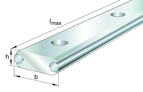

LFS52-FE
Guideway
flat solid profile, fixing hole spacing half of standard, with two raceway shafts; corrosion-resistant design possible
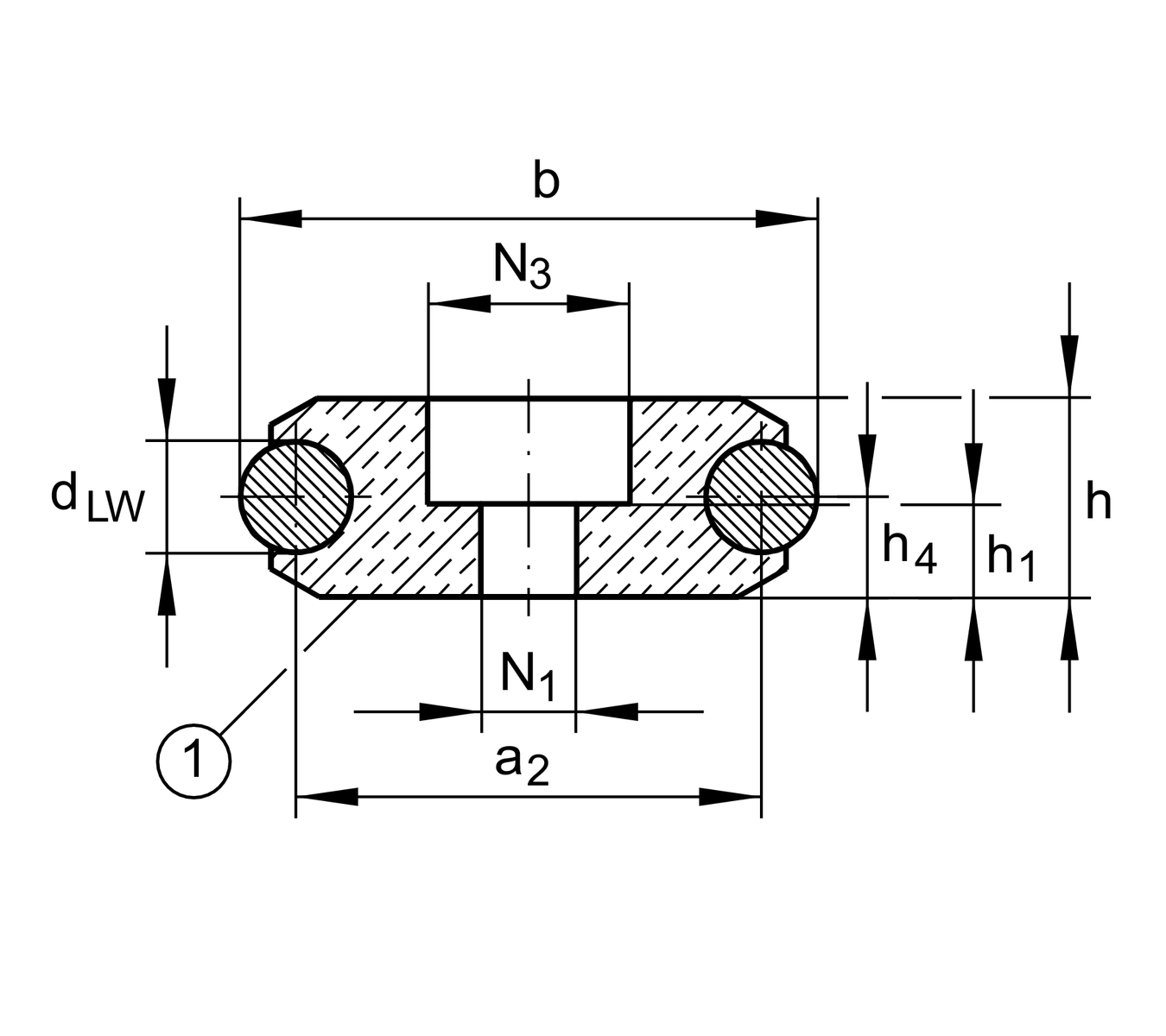
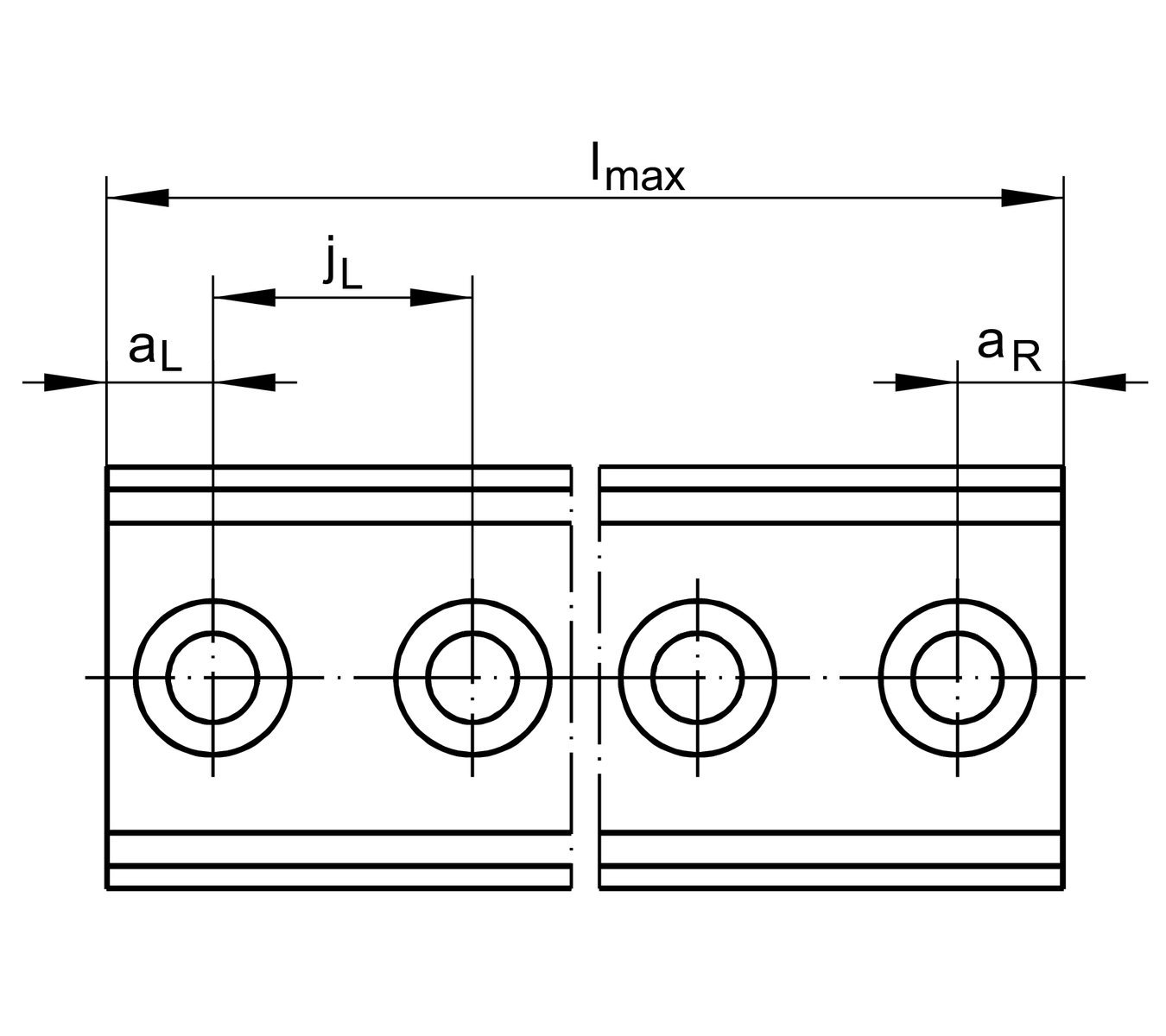
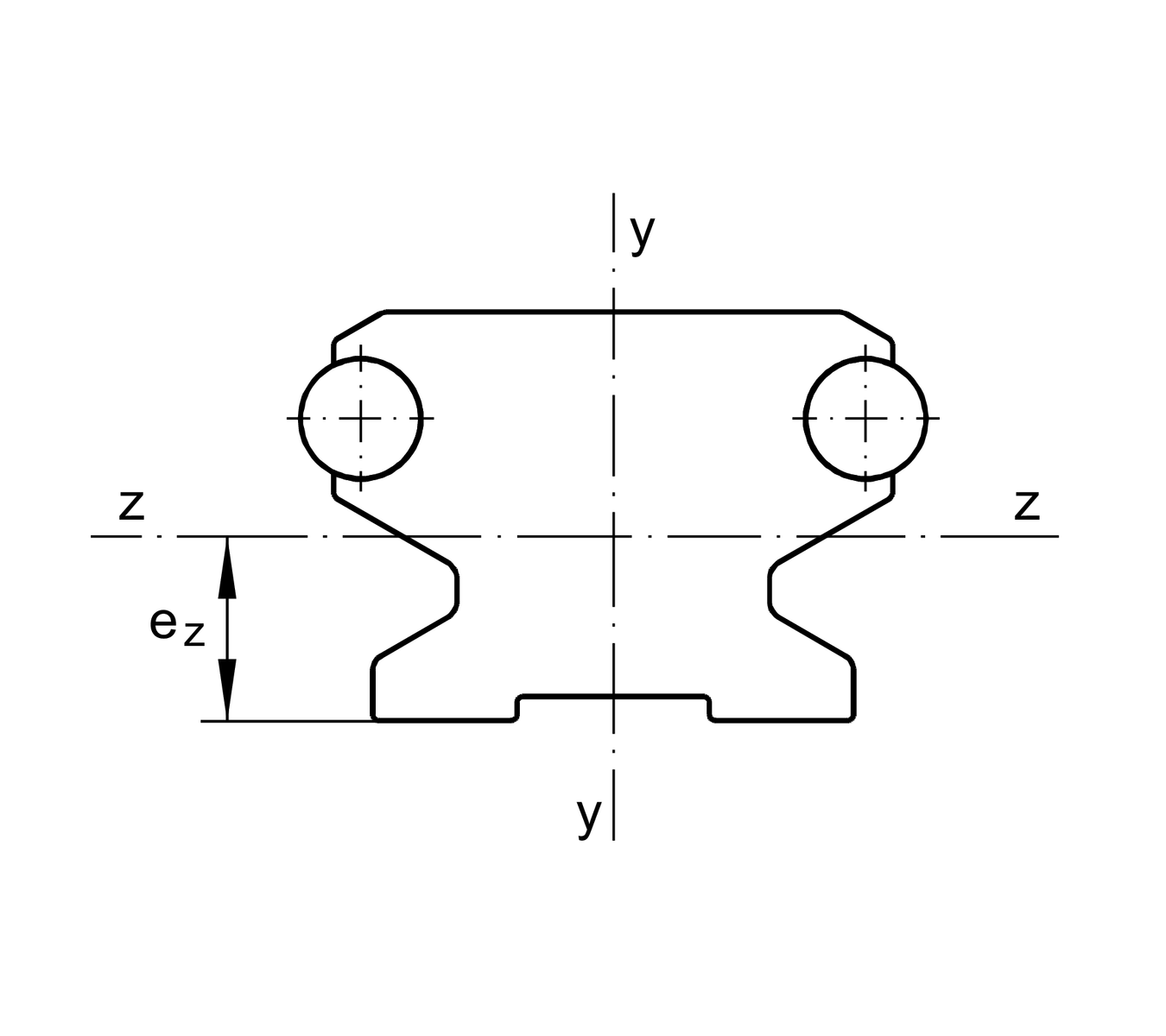
Main Dimensions & Performance Data
| h | 18 mm | Height |
| b | 52 mm | Width |
| lmax | 6,000 mm | Length maximum 1 |
| ly | 84,000 mm⁴ | Second moment of area |
| lz | 19,900 mm⁴ | Second moment of area |
| LFQ | 670 mm² | Cross-sectional area 2 |
| Wy | 3,610 mm³ | Wider resistance torque |
| Wz | 2,211 mm³ | Wider resistance torque |
Mounting dimensions
| N1 | 11 mm | Bore diameter 3 |
| N3 | 19 mm | Bore diameter 4 |
Dimensions
| a2 | 42 mm | Distance |
| aL max | 110 mm | Distance 5 |
| aL min | 17 mm | Distance 5 |
| aR max | 110 mm | Distance 5 |
| aR min | 17 mm | Distance 5 |
| dLW | 10 mm | Diameter |
| eZ | 9 mm | Distance |
| h1 | 8 mm | Height 6, 7 |
| h4 | 9 mm | Height |
| jL | 125 mm | Increment 8 |
Footnotes
1
Maximum length of single-piece guideways.
Longer guideways are supplied as several segments and are marked accordingly.
2
Value for cross-sectional area.
3

4
Under maximum load Fz and F0z, support washers to DIN 433 and the maximum tightening torque (see mounting instructions) are required.
5
aL and aR are dependent on the guideway length.
6
If support washers to DIN 433 are used, screws to DIN 7984 are recommended.
7
Counterbore depth for screws to DIN 7984.
8
Recommended screw pitch.
Underside marked.
Modulus of elasticity for LFS..: 72 000 N/mm2.
Downloads:
Your current product variant
| Size code | 52 | |
| Design | F | Flat solid profile |
| Locationg guideway | E | Fixing hole spacing half of standard |


