Guideways
Features
Designs
Guideway | Design |
|---|---|
LFS | With solid profile |
| |
LFS..-C | With hollow section profile (low mass) Location from above through holes Ends of hollow sections closed off |
| |
LFS..-F | Flat guideway Preferably for applications with Location from above through holes. |
| |
LFS..-M | With support rail giving high bending rigidity The support rail can be incorporated The end faces of the hollow sections are closed off using plastic end covers. |
| |
LFSR | Curved guideway element made from steel Location from above through holes Combinations of curved guideway elements |
| |
LFS120 | Wide, low guideway With recesses for toothed racks Location from above through holes. |
| |
LFS..-FH | Flat guideway with only one shaft as raceway Mainly for applications with Location from above through holes. |
| |
LFS..-N, LFS..-NZZ | With T-slot for location from below The upper slot in the guideways and Supplied with special support washers |
| |
TSN | Composite unit, aluminium support rail with screw mounted raceway shaft Location from above See Catalogue WF1. |
|


Guideways without fixing holes
All LFS guidances with the exception of LFSR are also available without fixing holes; suffix OL.
Design and safety guidelines
Guideway hole patterns
Unless specified otherwise, guideways have a symmetrical hole pattern, ➤ Figure.
Upon request, an asymmetrical hole pattern may be available. In this case, aL ≧ aL min and aR ≧ aR min.
Hole patterns of guideways with one row of holes


Hole pitch values
The hole pitch values jL are stated in the dimension tables. For high loads, guideways are available with reduced hole pitch values jL, ➤ Figure.
These guideways have the suffix E or EE; examples: LFS..-E, LFS..-EE.
Hole spacings jL

Maximum number of pitches between holes
The number of pitches between holes is the rounded down whole number equivalent to: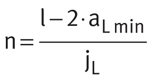 The spacings aL and aR are generally determined as follows:
 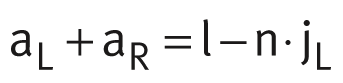 For guideways with a symmetrical hole pattern:
 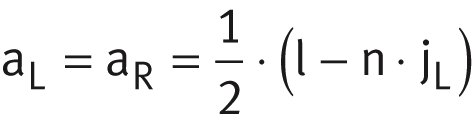 Number of holes:
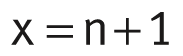
| n | – | Maximum possible number of pitches between holes |
| l | mm | Guideway length |
| aL min, aR min | mm | Minimum values for aL, aR |
| jL | mm | Spacing between holes |
| aL, aR | mm | Spacing between start or end of guideway and nearest hole |
| x | – | Number of holes. |
ACHTUNG
If the minimum values for aL and aR are not observed, the counterbores of the holes may be intersected.
Guideways without holes
All guideways LFS are also available without holes, with the exception of LFSR. These guideways have the suffix OL, for example LFS..-OL.
Multi-piece guideways
If the guideway length required is greater than lmax, the guideways are assembled from two or more sections matched to each other and marked accordingly. The sections may be of different lengths. The guideway joint is always arranged centrally between the fixing holes, ➤ Figure.
Multi-piece guideways

Accuracy of joint position
In order to achieve accuracy of the joint position, additional fixing is recommended for guideways from size 32 if the spacing C7 is larger than the stated limit value, see table and ➤ Figure.
In these cases, the guideways are supplied with the additional fixing hole already made.
Spacings for additional hole
Guideway | Spacing between hole and end of guideway | |
|---|---|---|
C7 Limit value | C8 Limit value | |
mm | mm | |
LFS32 (-C, -F) | 30 | 11 |
LFS42-C | 50 | 17 |
LFS52 (-C, -F) | 50 | 17 |
LFS86-C | 50 | 17 |
LFS120 | 50 | 17 |
Additional hole

Two guideways LFS can have a deviation relative to each other at the joint position of:
- Δb = ±0,01 mm
- Δh4 = ±0,05 mm , ➤ Figure .
Deviation at the joint position on guideways assembled from sections
