Accessories
Braking and clamping element
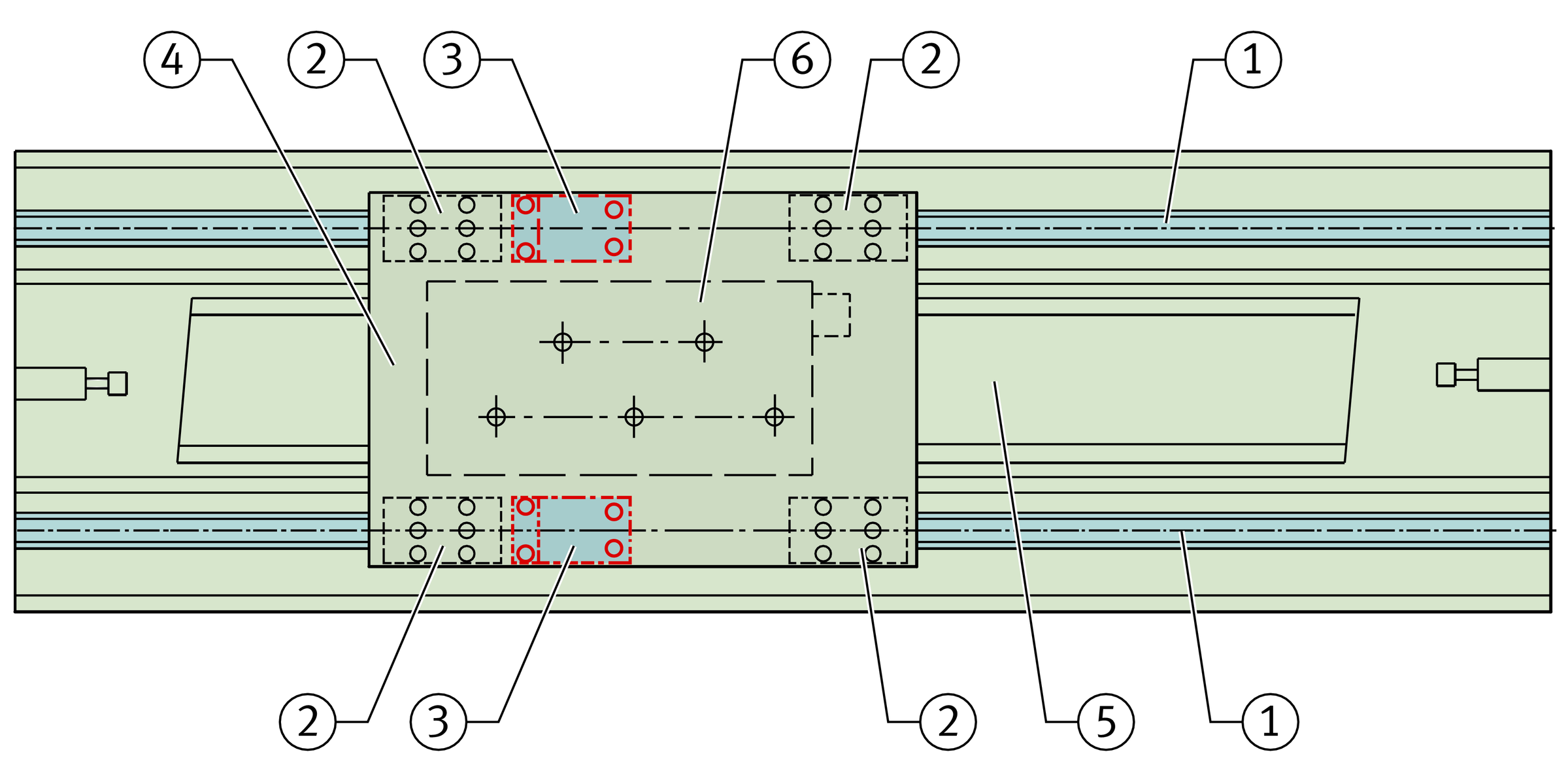
The braking and clamping element BKE.TKSD is used, for example, as a positionally independent security system for linear drives where the drive cannot fully provide the braking and clamping function, ➤ Figure.
The compact construction and the arrangement of the elements saves space and no special devices are required.
If particularly high braking forces are required, several braking and clamping elements can be fitted.
The system automatically compensates any clearance occurring up to the wear limit of the brake shoes, see link. The elements are thus maintenance-free.
Braking and clamping element
Mechanical braking and clamping forces
The elements operate by purely mechanical means, they therefore function even if a power failure occurs and are reliable in any mounting position. The brake shoes are opened by hydraulic means. If the pressure drops or the power fails, the brake shoes are closed again. This eliminates safety problems resulting from power failure, which is a possibility with electronically braked systems.
The system carries out braking when no pressure is present. This allows safety-focussed control even in emergencies. The hydraulic brake opens under a pressure of approx. 55 bar.
If appropriate control is provided, even vertical axes can be rapidly braked to a stationary position. In a suspended arrangement, however, the entire guidance unit should be secured by a drop guard.
ACHTUNG
When the brake is locked, an axial clearance of up to 0,25 mm can occur. This must be observed if the elements are used for fixing.
Short reaction time
The clearance-free adjustment of the brake shoes ensures a short, consistent reaction time (in the case of size 35, for example, of <30 ms).
ACHTUNG
Braking and clamping elements are one part of the emergency braking system. Their reliable operation also depends on the hydraulic components and the control system.
Function
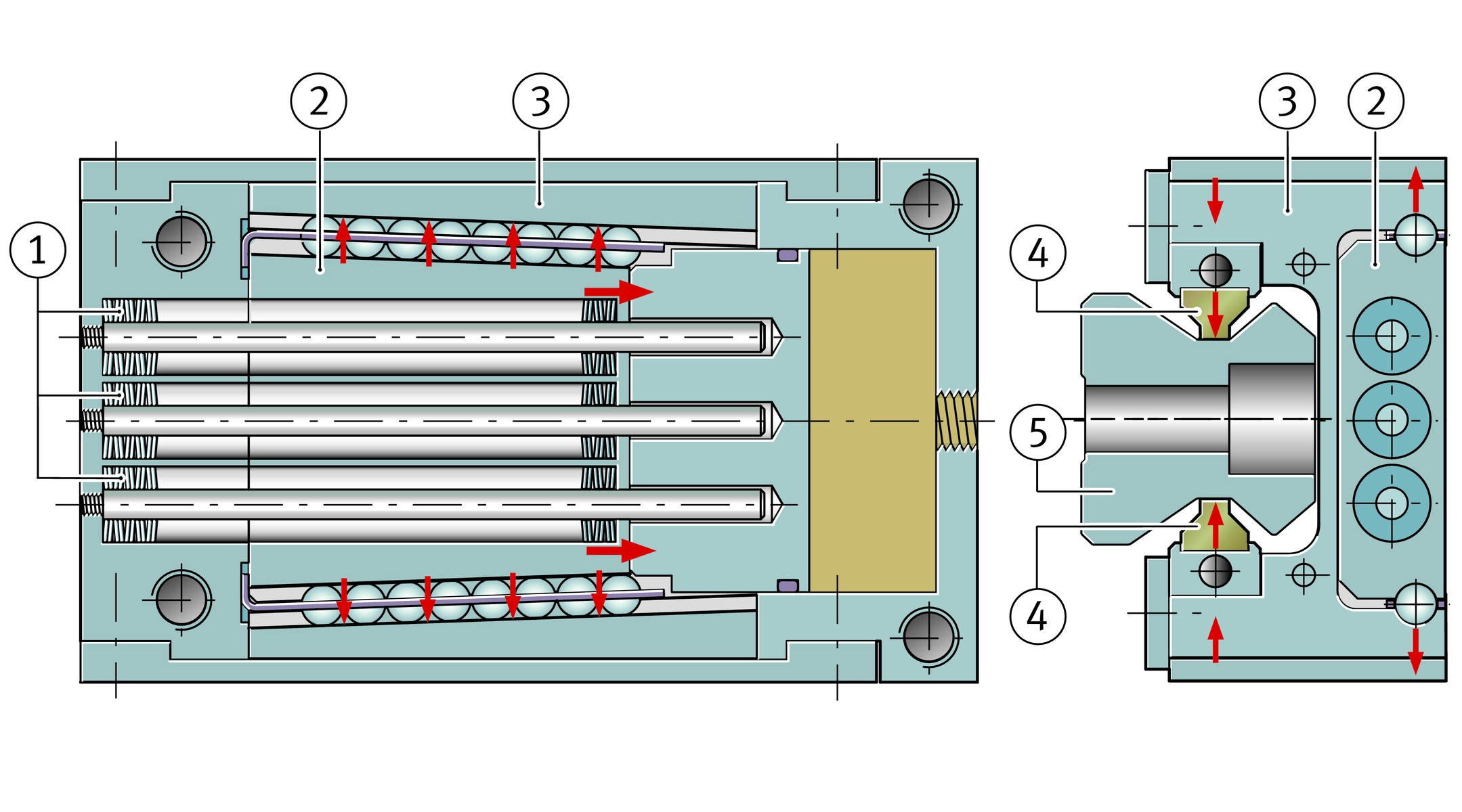
Three disc spring columns generate the braking and clamping force, ➤ Figure. Thanks to this mechanical spring energy store, the system operates extremely reliably without external energy.
The force is transmitted to the brake shoes by mechanical means. If the braking or clamping function is activated, the spring columns push a wedge-shaped slider between the upper legs of the H-shaped saddle plate. This presses the upper legs outwards and the lower ones inwards. The brake shoes clamp against the guideway, but not on the raceways.
Functional components


Operating pressure of braking and clamping elements
Operating pressure | |
|---|---|
min. | max. |
> 55 bar | 90 bar |
ACHTUNG
Pressure spikes of more than 90 bar must be avoided in all cases. Comprehensive information can be found in the mounting manual MON 01, Braking and Clamping Elements.
Wear of brake shoes
Since the system performs not only a clamping function on stationary guidance systems but also a braking function on moving guidance systems, wear of the brake shoes occurs. However, clearance between the brake shoes and brake contact surfaces increases the system reaction time.
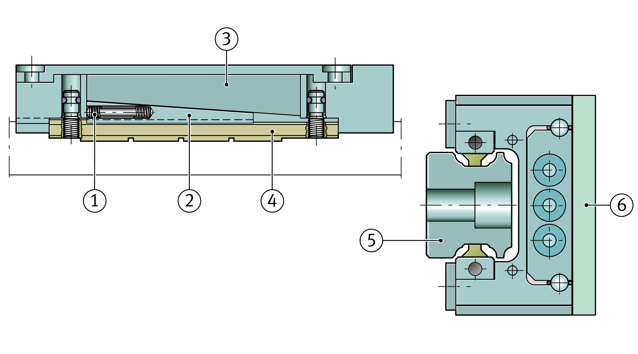
Automatic clearance compensation
For reliable functioning of the system, the brake shoes must always be in clearance-free contact. In order to ensure consistent clearance-free contact of the brake shoes against the contact surfaces, wear of the linings is automatically compensated by mechanical means up to the wear limit. Disc spring assemblies slide a wedge between the brake shoes and the saddle plate, ➤ Figure. This ensures that the element always operates without clearance. The wear compensation mechanism is designed such that, in the opened condition, the brake shoes are adjacent to but not in contact with the guideway surface. This ensures that there is no wear or displacement resistance during travel.
Adapter plate
For the H variant of the carriages, an adapter plate is necessary, ➤ Figure. The adapter plate is included in the scope of delivery.
Wear compensation
and adapter plate

Ease of mounting
Braking and clamping elements are particularly easy to fit. They are simply slid onto the guideway and screw mounted to the adjacent construction.
ACHTUNG
Due to the automatic wear compensation system, braking and clamping elements must be slid directly from the dummy guideway onto the guideway.
The element must never be separated from the guideway without using a dummy guideway and the dummy guideway must never be removed from the element.
Suitable for ...
The elements give high braking and clamping forces but have only a very small design envelope. They are matched in their dimensions to the INA standard and H design carriages. The elements are available for the monorail guidance systems RUE-E, KUSE and KUVE-B and can be integrated without any problems in existing applications with INA linear guidance systems.
The compact construction and the arrangement of the elements directly on the guideway saves space and thus allows complete constructions with a reduced number of components.
They can also be used in applications without recirculating rolling element systems. In this case, the guideway is used as a braking or clamping rail.
Typically, the braking and clamping element is arranged between two carriages on the table and acts as an emergency brake, ➤ Figure.
Typical application
Delivered condition
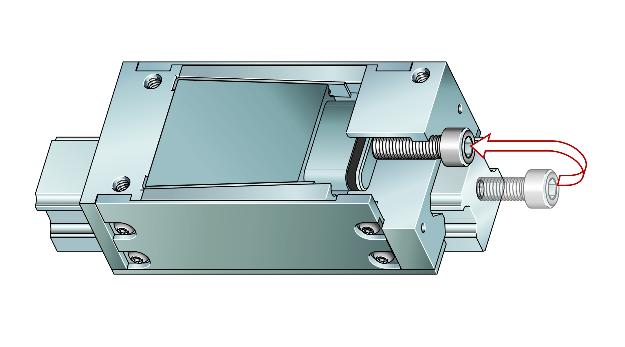
The elements are premounted on a separate support rail and clamped in place by means of a fitting screw, ➤ Figure. The screw is used to loosen and then move the fixed element. The fitting screw is later replaced by the hydraulic connector.
Braking and clamping element on support rail