Shaft and support rail units
Features
Shaft and support rail units TS..W are composite units comprising a raceway shaft screw mounted to an aluminium support rail. The shaft protrudes approx. 2 mm to 3 mm beyond the end of the support rail at both ends.
The raceway shaft is made from quenched and tempered steel. Corrosion-resistant design available by agreement.
Shaft and support rail units are composed of several individual sections depending on their length.
Shafts made from special materials such as those with coatings are available by agreement.
Multi-piece raceway shafts and shaft and support rail units
If the guidance systems are of such a length that shaft and support rail units TS..W cannot be achieved using single-piece shafts, shafts and support rails are supplied as multi-piece units, ➤ Figure. The joint locations on the shaft sections have mortice and tenon joints and are polished.
The joint locations on the shafts and support rails are offset from each other.
The maximum length of single-piece shaft and support rail units is 6 000 mm.
Shaft and support rail unit
with multiple support rail sections


Design and safety guidelines
Hole patterns for shaft and support rail units
Unless stated otherwise, raceway shafts and shaft and support rail units are supplied with a symmetrical hole pattern, ➤ Figure to ➤ Figure.
An asymmetrical hole pattern may be available at customer request. In this case, aL max ≧ aL ≧ aL min and aR max ≧ aR ≧ aR min.
Hole patterns for shafts
with one row of holes


Hole patterns for support rails
with two rows of holes


Hole patterns
for shaft and support rail unit TSUW


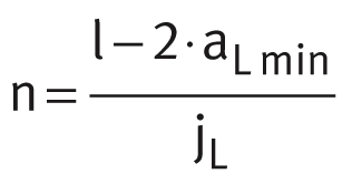
Maximum number of pitches between holes
The number of pitches between holes is the rounded whole number equivalent to: The distances aL and aR are generally determined by:
 For raceway shafts and shaft and support rail units with a symmetrical hole pattern:
 Number of holes:
| n | mm | Maximum possible number of pitches or recommended distance between screws on shaft and support rail units with T-slots |
| l | mm | Length of shaft and support rail unit |
| aL, aR | mm | Distance between start or end of shaft and support rail unit and nearest hole |
| aL min, aR min | mm | Minimum values for aL, aR according to dimension tables |
| aL max, aR max | mm | Maximum values for aL, aR according to dimension tables |
| jL | mm | Distance between holes |
| x | mm | Number of holes on shaft and support rail units with T-slots: number of screws. |
ACHTUNG
If the minimum and maximum values for aL and aR are not observed, the counterbores of the holes may be intersected. The position aL for shaft and support rail unit TSUW is shown in ➤ Figure .
Accuracy
Length tolerances
for shafts and shaft and support rail units
The length tolerances are shown in the table.
Tolerances
Length of shaft or shaft and support rail unit L | Length tolerance | |||
|---|---|---|---|---|
mm | mm | |||
Single-piece and multi-piece raceway shaft and support rail units | ±0,1% of total length | |||
| L ≦ | 400 | ±0,5 | |
400 | < | L ≦ | 1 000 | ±0,8 |
1 000 | < | L ≦ | 2 000 | ±1,2 |
2 000 | < | L ≦ | 4 000 | ±2 |
4 000 | < | L ≦ | 6 000 | ±3 |

