
Hydrostatic compact guidance system
Features
The carriages in monorail guidance systems based on rolling contact cannot accommodate vibration damping. In order to allow appropriate damping of vibrations from the adjacent construction, additional elements such as the passive damping carriage RUDS-D for the linear recirculating roller bearing and guideway assemblies RUE-E are necessary, which is positioned between the carriages. In order to have the greatest effect when bending vibrations occur, however, the damping element must be positioned at the point of largest deflection. For this reason, knowledge of the vibration modes is absolutely necessary.
X-life
Hydrostatic compact guidance systems HLE45-A-XL are supplied in X-life quality.
Since there are no rolling elements present, the guidance system is not subject to wear under rolling contact, so the operating life can be exceeded many times over in comparison with conventional monorail guidance systems.
Hydrostatic vibration damping within the design envelope of a monorail guidance system
For applications with very high demands on damping, dynamic rigidity, very good running characteristics and load carrying capacity, there is now a hydrostatic compact guidance system based on our proven linear recirculating roller bearing and guideway assemblies RUE..-E for size 45.
This sealed and preloaded guidance system is a complete unit. Through use of the hydrostatic compact guidance system, vibration can be damped irrespective of position, directly at the bearing seat and there is no longer any requirement for retrofitting with damping-specific components.
The guidance systems combine damping values of more than 470 000 kg/s with levels of tensile/compressive rigidity that are almost as high as the rigidity of the corresponding rolling element guidance systems. When used in machine tools, this gives higher cutting output, better surface quality and longer tool life.
A special bronze coating in the pressure pockets of the saddle plate gives excellent emergency running characteristics, which means that the guidance system is not damaged immediately even when overloaded or during operation without hydraulic pressure.
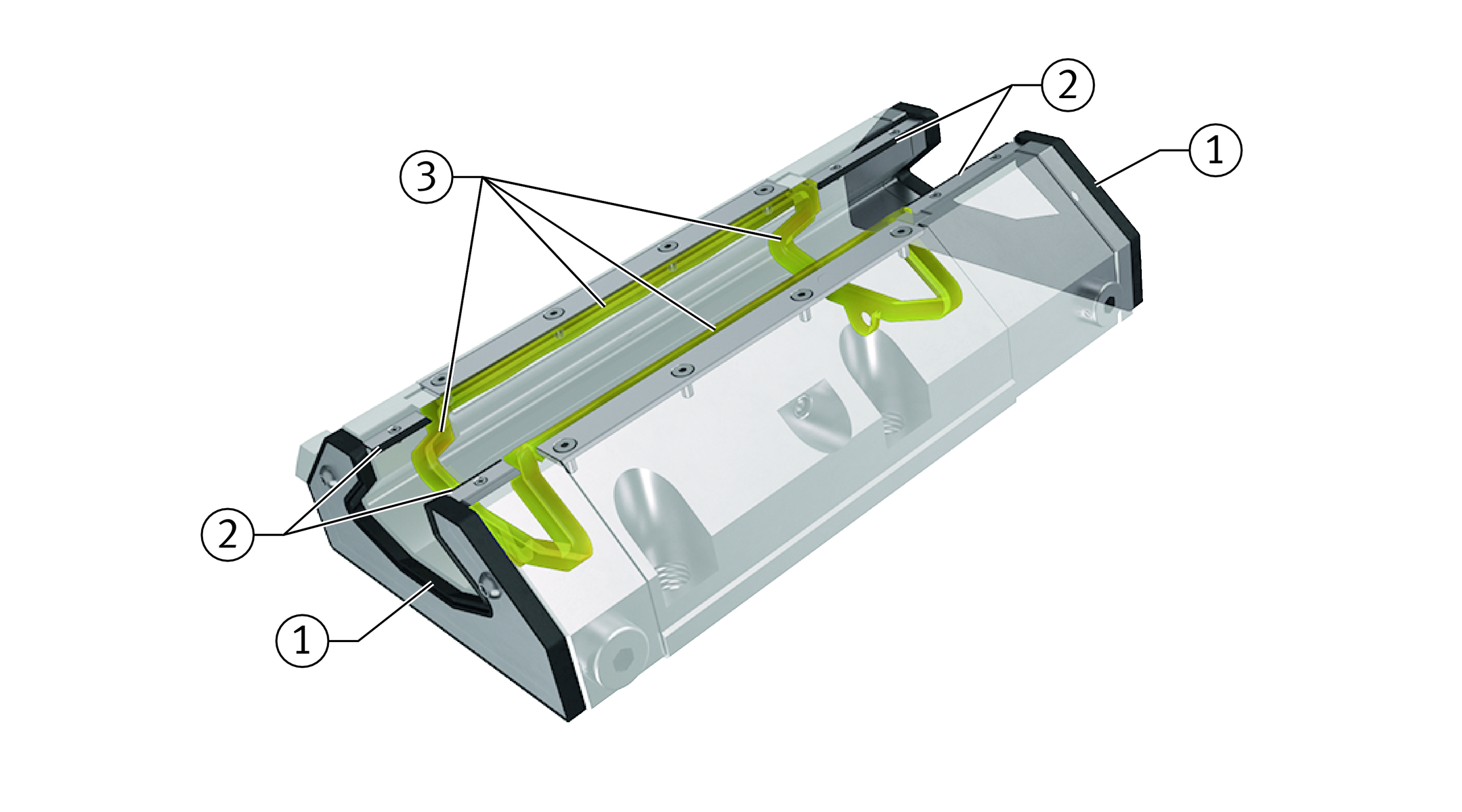
Functional principle
A carriage has one pressure pocket per raceway that is subjected to the pressure of hydraulic oil. The oil is fed to the pressure side under a continuous pressure of 100 bar. The end piece on the pressure side contains flow control valves. These are supplied already set to optimum values and control the oil flow rate for all pressure pockets, so setting by the customer is not necessary. This ensures that the maximum forces can be supported.
After the oil has left the pressure pocket, the hydraulic oil is approximately unpressurised, is extracted from the compact guidance system on the suction side and can be fed back to the oil circuit.
The carriage has an inner seal on all faces that retains the oil in the carriage. As a result, leakage is reduced to a minimum. It is not necessary to collect the oil as in the case of conventional hydrostatic guidance systems. For sealing, see link.
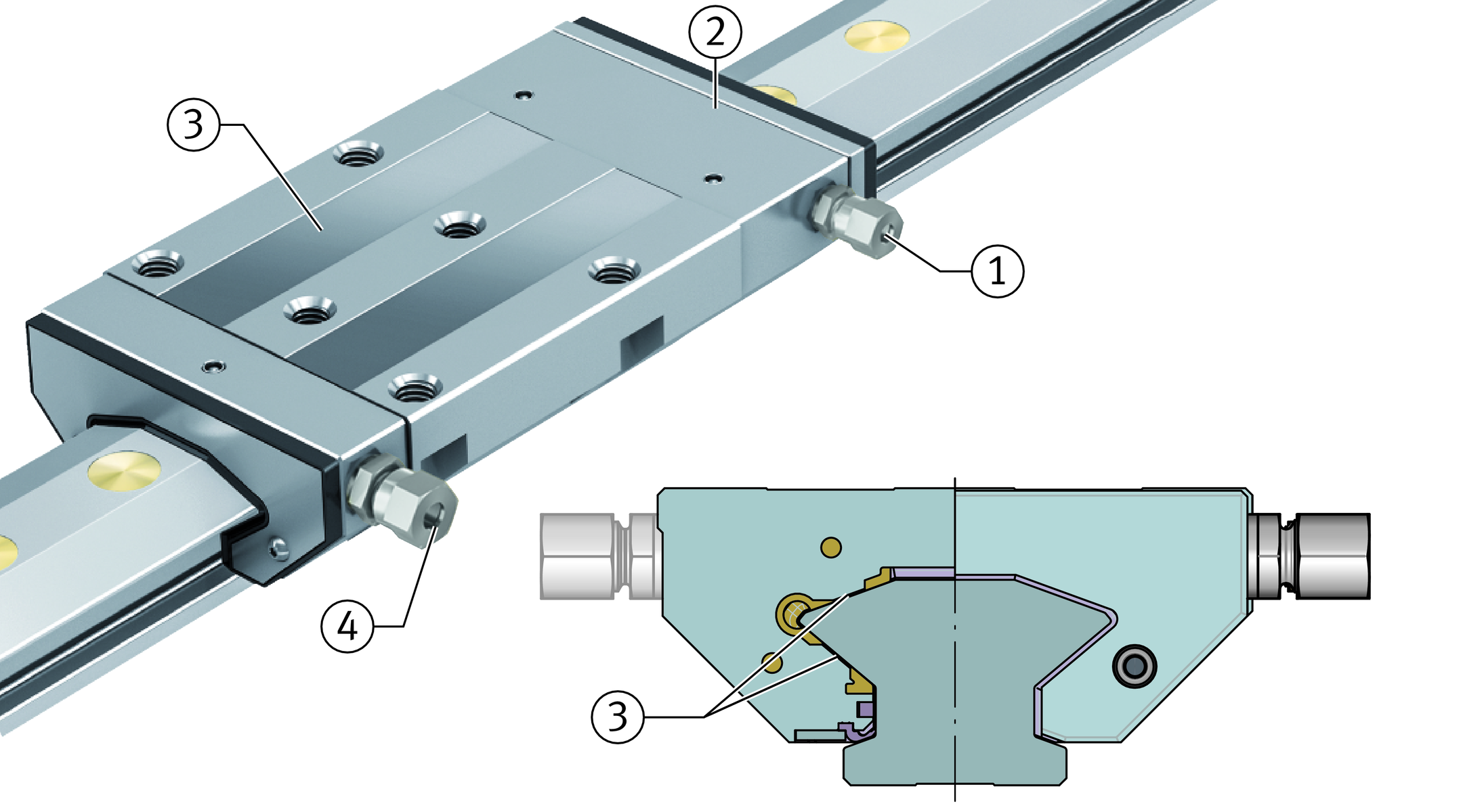
Functional parts


Advantages of this solution
Due to the integral hydraulic control mechanism, the hydrostatic guidance system is ready to fit and can be integrated into the standard design envelope of a linear recirculating roller bearing and guideway assembly.
The demanding adjustment in the mounting of conventional hydrostatic guidance systems is completely eliminated in the case of the hydrostatic compact guidance system HLE45. Furthermore, the hydrostatic compact guidance system does not require complex machining processes on the surfaces in order to achieve optimum gap dimensions, since these are already defined by the system.
Since a carriage can support forces in all directions, except in the direction of motion, its design integration is significantly easier because a counterstay is not required.
Only one machine concept required
As a result of compliance with the DIN design envelope, the DIN mounting dimensions for monorail guidance systems (identical geometrical mounting dimensions and identical outline profile) and the excellent damping characteristics of the hydrostatic compact guidance system, several performance classes are possible with a single machine concept. As a result, just one concept can be used to cover various requirements in relation to machining.
Depending on the priority, the following examples are possible:
- excellent surface quality and accuracy in normal machining
- increased cutting rate and cutting depth with high machining quality and accuracy in high performance machining.
Carriages
The saddle plate of the carriages is made from steel, while the pressure pockets in the saddle plate have a special bronze coating. End pieces are mounted on both sides of the saddle plate which ensure the entry and exit of oil.
Guideways
The guideways are made from hardened steel and ground on all sides. The raceways that form the oil gap together with the saddle plate are ground to extremely high precision.
Location from above
Guideways TSH are located from above and have through holes with counterbores for the fixing screws.
Multi-piece guideways
If the required guideway length lmax is greater than the value in the dimension tables, the guideways are supplied as several segments, see link.
Standard accessories
Brass closing plugs
The closing plugs close off the counterbores of the guideway holes flush with the surface of the guideway.
Load carrying capacity
The units can support loads from all directions, except in the direction of motion. In order to facilitate the support of additional moments about all axes, the arrangement must have at least two guideways and four carriages.
A costly counterstay system, as known from conventional hydrostatic guidance systems, is not necessary.
Acceleration and velocity
The hydrostatic compact guidance system is suitable for accelerations up to 100 m/s2 and velocities up to 2 m/s, see table.
Operating limits
Designation | Acceleration up to | Velocity up to |
|---|---|---|
m/s2 | m/s | |
HLE | 100 | 2 |
Interchangeability
The carriages and guideways are interchangeable and can therefore be freely combined with other guideways and carriages.
Sealing
Elastic seals on the end faces and sealing strips on the undersides of the carriages protect the system against contamination. The carriage has an inner seal on all faces that retains the oil in the carriage. As a result, leakage is reduced to a minimum. A single lip seal made from high performance material fitted to both sides of the carriage additionally protects the interior of the carriage against wear and the ingress of contamination, ➤ Figure.
ACHTUNG
Where heavy contamination load or aggressive media are present, additional covers should be used to protect the guidance system.
Standard sealing concept
Operating conditions
For operation of a hydrostatic compact guidance system, a hydraulic oil HLP 46 corresponding to classification in accordance with DIN 51524-2 is required. The oil corresponds to the viscosity grade ISO VG 46 and must be filtered to a particle size of 10 μm.
The operation of a carriage requires 1,3 l/min of hydraulic oil HLP 46. If the hydrostatic compact guidance system is to be operated using a hydraulic oil of a different viscosity grade, this will have effects on the rigidity, load carrying capacity and flow rates.
Furthermore, a hydraulic unit including extraction (optionally an extraction module), see link, and a cooling system is necessary.
Operating temperature
The compact guidance system is designed for a hydraulic oil HLP 46 in the temperature range from +20 °C to +34 °C. In this range, the rigidity, load carrying capacity and flow rate are approximately constant.
Corrosion-resistant design
There is no corrosion-resistant design of the hydrostatic compact guidance system.
Designs
The hydrostatic compact guidance system HLE is available in one design.
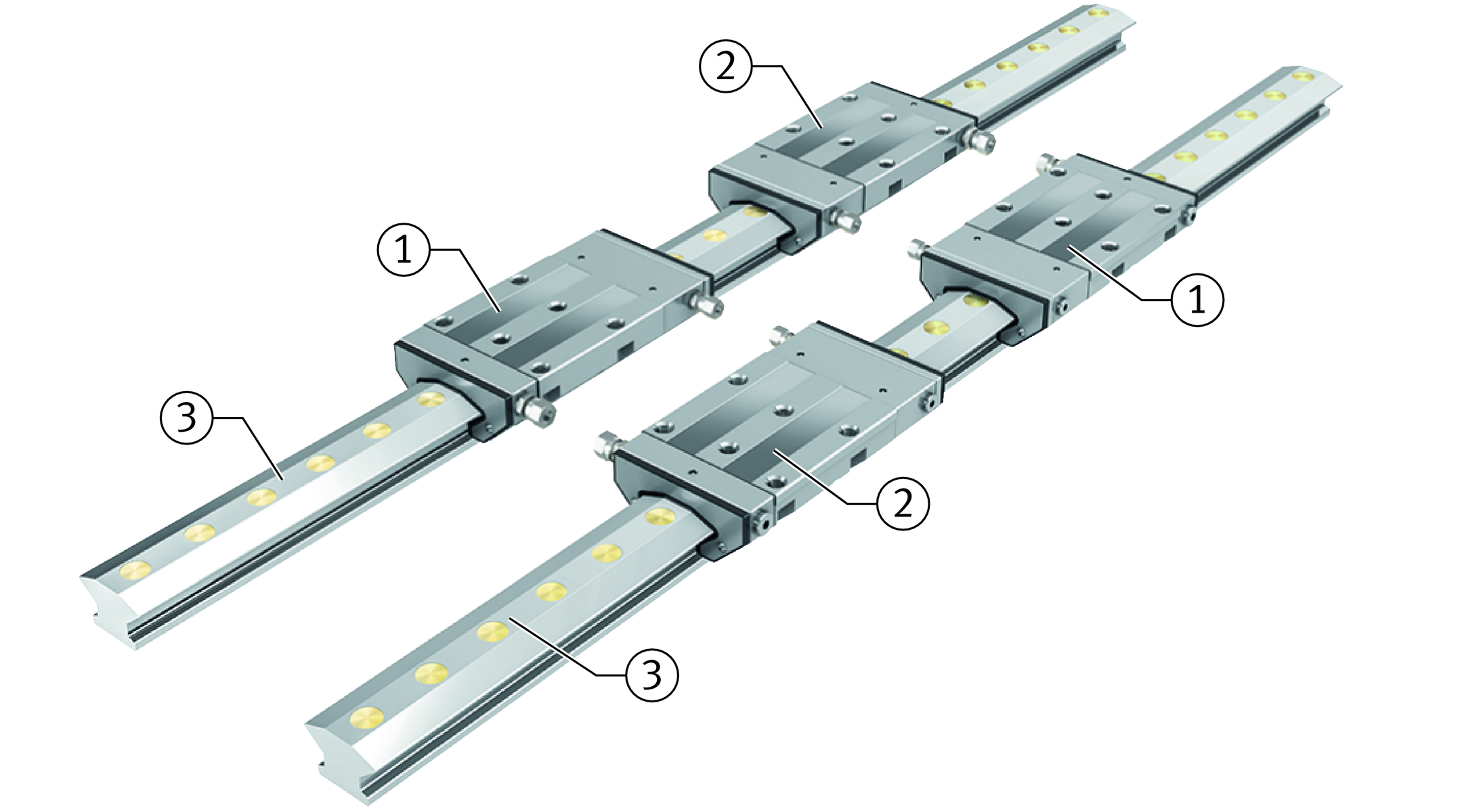
Available designs
A hydrostatic system comprises at least two guideways TSH45-XL each with two carriages (1×HLW45-A-SR-XL and 1×HLW45-A-SL-XL) and brass closing plugs KA20-M to close off the fixing holes in the guideways. As an option, Schaeffler offers a conical closing plug KA20-M-konisch made from brass, which ensures even lower oil discharge.
The guideways are supplied as a single piece up to a maximum length of 2 800 mm; guideways comprising joined segments are permissible.
Design and safety guidelines
The flow control valves in the carriage are preset to the relevant flow rate.
ACHTUNG
A system with hydrostatic compact guidance systems always comprises at least two guideways each with two carriages, ➤ Figure . It is not possible to design a system with only one guideway or one carriage.
Hydrostatic guidance system
Preload
At an input pressure of 100 bar, the guidance unit HLE45-A-XL in a load-free state is preloaded to a pressure of approx. 50 bar per raceway (pressure pocket).
Friction
The friction in the hydrostatic compact guidance system results almost exclusively from the friction of the integrated seals. Due to the absence of rolling element recirculation, the displacement resistance of the HLE is very constant and, with correct extraction from the carriage, is approx. 20 N per carriage. If the dynamic pressure on the carriage is greater than 0,2 bar, this will lead to an increase in friction and possibly to leakage, see link. The friction is independent of load until the load limit is reached (positioning of the carriage on the guideway).
Rigidity
The rigidity per carriage is as follows:
in a compressive direction | = | 1 200 N/μm | |
in a tensile direction | = | 900 N/μm | |
in a lateral direction | = | 500 N/μm. |
The values were determined under an input pressure of 100 bar. They include the deformation of the hydrostatic guidance unit HLE , including the screw connections to the adjacent construction.
ACHTUNG
The rigidity curves are valid only for mounting using six screws and an appropriate oil supply, see link.
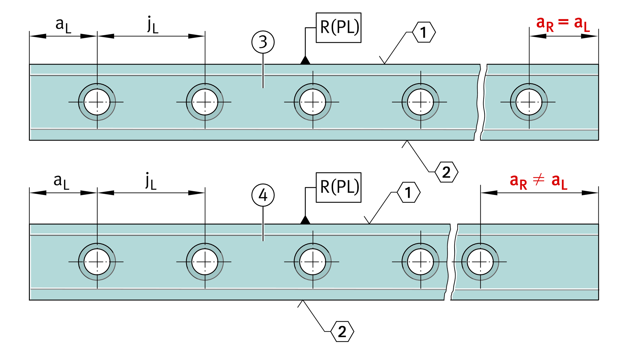
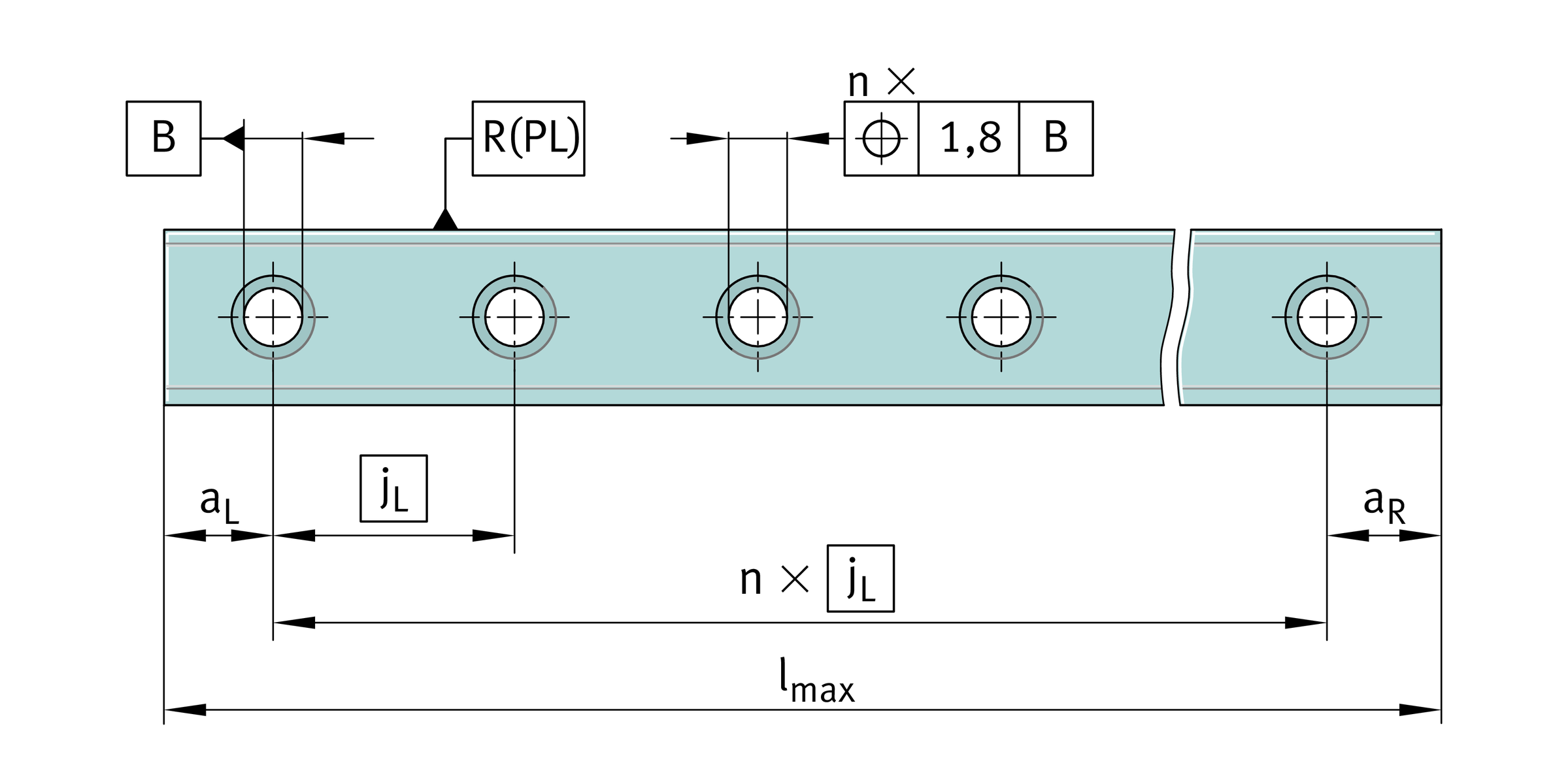
Hole patterns of guideways
Unless specified otherwise, the guideways have a symmetrical hole pattern where aL = aR, ➤ Figure.
An asymmetrical hole pattern may also be available upon request. In this case, aL ≧ aL min and aR ≧ aR min, ➤ Figure.
ACHTUNG
If the locating face is on the top, aL is on the left and aR on the right, ➤ Figure.
Hole patterns of guideways with one row of holes


Maximum number of pitches between holes
The number of pitches between holes is the rounded down whole number equivalent to: The spacings aL and aR are generally determined as follows:
  For guideways with a symmetrical hole pattern:
  Number of holes:
| n | Maximum possible number of pitches between holes | |
| l | mm | Guideway length |
| aL min, aR min | mm | Minimum values for aL, aR |
| jL | mm | Spacing between holes |
| aL, aR | mm | Spacing between start or end of guideway and nearest hole |
| x | Number of holes. |
ACHTUNG
If the minimum values for aL and aR are not observed, the counterbores of the holes may be intersected. Risk of injury.
Multi-piece guideways
If the guideway length required is greater than lmax or joined guideways are required, these guideways are assembled from segments that together comprise the total length. The segments are matched to each other and marked. The pitch is always located centrally between the fixing holes.
Marking of multi-piece guideways
1A, 1A 1B, 1B 1C, 1C
2A, 2A 2B, 2B 2C, 2C
ACHTUNG
In order to achieve the necessary integrity, the guideway segments must be bonded to each other by adhesive. Observe the guidelines in the mounting manual MON 50.
Demands on the adjacent construction
The running accuracy is essentially dependent on the straightness, accuracy and rigidity of the fit and mounting surfaces.
The straightness of the system can be achieved most easily when the guideway is pressed against a locating face.
Geometrical and positional accuracy of the adjacent surfaces
The higher the requirements for accuracy and smooth running of the guidance system, the more attention must be paid to the geometrical and positional accuracy of the mounting surfaces.
ACHTUNG
Observe the tolerances according to ➤ Figure.
Surfaces should be ground or precision milled with the objective of achieving a mean roughness value Ramax 1,6.
Any deviations from the stated tolerances will reduce the overall accuracy and impair the function.
Height difference ΔH
For ΔH, permissible values are in accordance with the following equation. If larger deviations are present, please contact us.

| ΔH | μm | Maximum permissible deviation from the theoretically precise position, |
| a | Factor dependent on preload class, in this case: 0,075 | |
| b | mm | Centre distances between guidance elements. |
Tolerances of mounting surfaces and parallelism of mounted guideways and carriages
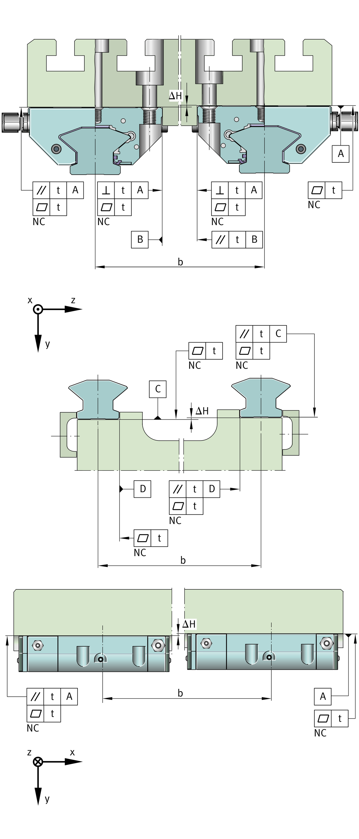
Parallelism of mounted guideways
For guideways arranged in parallel, the parallelism tolerance t should be in accordance with ➤ Figure, and table.
Parallelism tolerance t of guideways
Designation | Parallelism, flatness and perpendicularity t |
|---|---|
μm | |
TSH45-XL | < 10 |
ACHTUNG
If the maximum values are used, this may increase the displacement resistance.
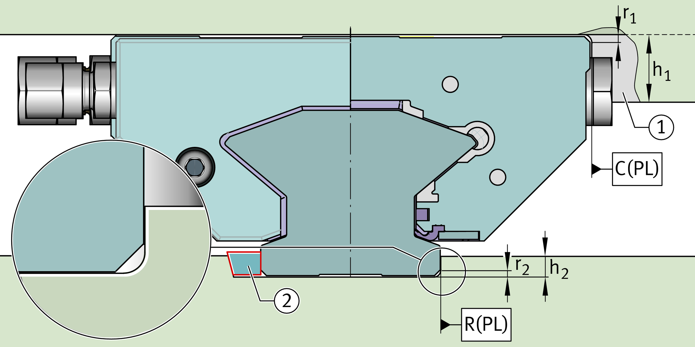
Locating heights and corner radii
The locating heights and corner radii must be matched to the compact guidance system, see table and ➤ Figure.
The adjacent construction must include a recess for the closing plugs and the pipe screw connectors, ➤ Figure.
Locating heights, corner radii
Designation | h1 | h2 | r1 | r2 |
|---|---|---|---|---|
mm | mm | mm | mm | |
HLE45-A-XL | 10 | 8 | 1 | 0,8 |
Locating heights and corner radii
Mounting of the compact guidance system
ACHTUNG
Never slide the carriage onto the guideway without oil. Otherwise, the seals may be damaged.
Before the carriages are slid into place, the guideways must be aligned, firmly screwed down and the holes must be closed off using brass plugs. Otherwise, the seals may be damaged.
When using the hydrostatic guidance system, both guideways and one side of the carriages should have a fixed stop.
Before mounting the guideways and carriages, the mounting steps and warning messages in the mounting manual MON 50 must always be observed.
Mounting
Carry out mounting as described in the following steps:
- Slide the oiled carriage onto the guideway and move it to the mounting position without load.
- Make the hydraulic connection to the carriage (the positions of the pipe screw connectors for the oil connection lines and the closing plugs can be transposed to the other side if required).
- Apply the operating pressure to the system.
- Locate the mating part on the carriages.
- Screw in the carriage screw from the rear face of the carriage (from above).
The guidance system is thus ready for operation.
Hydraulic unit
Each carriage must have a volume flow of 1,3 l/min.
Inlet and outlet lines for the hydraulic system
The largest possible line diameters must always be selected.
Inlet line
In order to minimise the pressure losses due to pipe resistance, the pipe cross-section should only be reduced immediately before the connector to the carriage to an inside diameter of 4 mm. The pressure connector fitted to the carriage conforms to L6 (M12×1,5) in accordance with DIN EN ISO 8434-1 (the screw thread in the carriage is M10×1).
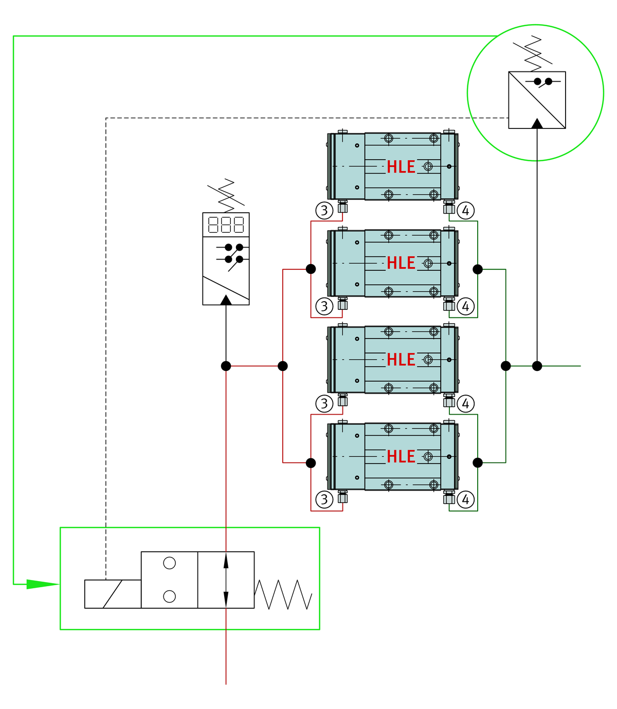
A shut-off valve should be fitted in the inlet pipe that will stop pressure being applied to the carriage if the pressure in the extraction pipe is too high (1 bar). This prevents damage to the system. The safety circuit is shown in the fluid diagram, ➤ Figure.
Outlet line
In the outlet pipe, the pipe resistance as far as the extraction pump for all connected carriages must be identical and as low as possible, in order to ensure uniform suction from all carriages. The pipe cross-section should be as large as possible and should only be reduced immediately before the connector to the carriage to an inside diameter of 6 mm.
The extraction connector fitted to the carriage conforms to L8 (M14×1,5) in accordance with DIN EN ISO 8434-1(the screw thread in the carriage is M12×1,5).
After exit from the carriage, the extraction pipe should be expanded after a maximum of 300 mm to an inside diameter of 16 mm in order to minimise the line resistance.
When using longer outlet pipes (> 2 m), the oil should be sucked out by the extraction module directly on the guidance axis. Through the use of the extraction module, the pipe cross-sections towards the unit can be reduced.
The dynamic pressure on the extraction side of the carriage must be less than 0,2 bar, in order to minimise leakage and friction of the guidance system. Where there are higher requirements relating to leakage and friction, there should be an underpressure on the extraction side of the carriage (up to –0,5 bar).
ACHTUNG
Pipe cross-sections should be designed in accordance with the volume flows. The pipe resistances of the extraction and pressure pipe must always be calculated; please consult us as necessary.
A pressure switch must be provided in the hydraulic unit that authorises motion of the hydrostatic axis in the controller only when sufficient pressure is present.
Movement and operation of the guidance system should only be carried out (despite the excellent emergency running characteristics) when the hydraulic system is active.
Example:
Hydraulic unit and extraction module from HYDAC for guidance systems HLE45-A-XL
The following examples are concepts only, which must be adapted to the corresponding requirements of the application. In partnership with the company HYDAC, a hydraulic unit and extraction module were configured as examples. The hydraulic unit was designed with 3 power levels for guidance systems with 4, 8 and 12 carriages. In order to provide the necessary cooling performance for the guidance system, the unit can be combined with a suitable compressor cooling system, ➤ Figure.
Hydraulic units
Features
The hydraulic unit configured with the company HYDAC has the following features:
- power level matched to 4, 8 or 12 carriages
- electronic monitoring of:
- contamination indicator on pressure side
- contamination indicator on extraction side
- oil level
- oil temperature
- pressure on pressure side
- pressure on extraction side
- pressure in the cooling loop
- filtration of oil on pressure side and return side
- in the case of ambient temperatures deviating from the specified range, see table, special tempering carried out as necessary.
Where there are long return distances to the hydraulic unit or when using energy chains, an additional extraction module is recommended in order to assist the return movement of oil.
The technical data for the hydraulic unit are indicated for guidance systems with different numbers of carriages, see table.
Technical data for hydraulic unit (HYDAC)
Characteristics | Design | ||||
|---|---|---|---|---|---|
Number of carriages | |||||
4 | 8 | 12 | |||
Motor | |||||
Rated frequency | Hz | 50 | |||
Rated speed | min–1 | 1 420 | |||
Connection voltage (threephase current) | V | 400 | |||
Rated power | kW | 2,2 | 4 | 5 | |
Pump | |||||
Volume flow | l/min | 5,2 | 10,4 | 15,6 | |
Volume flow with extraction module | l/min | 6,7 | 13,4 | 20,1 | |
Controller | |||||
Pressure setting | bar | 115 | |||
Duty cycle | |||||
Continuous operation | bar | Suitable | |||
Tank | |||||
Fill volume | l | 80 | 100 | 120 | |
Mounting position | ‒ | Horizontal | |||
Ambient temperature | |||||
min. | °C | –10 | |||
max. | °C | +30 | |||
Cooling system | |||||
Power of compressor chiller | kW | 1,5 | 3,3 | 5,8 | |
Heat exchanger | ‒ | HYDAC HEX S610 | |||
Pressure fluid | |||||
Mineral oil HL/HLP to | ‒ | HLP 46, DIN 51524-2 | |||
Oil temperature** | min. | °C | +20 | ||
max. | °C | +34 | |||
**The values are based on the recommended operating conditions of the hydrostatic compact guidance system. If other temperature requirements are present, please consult us.
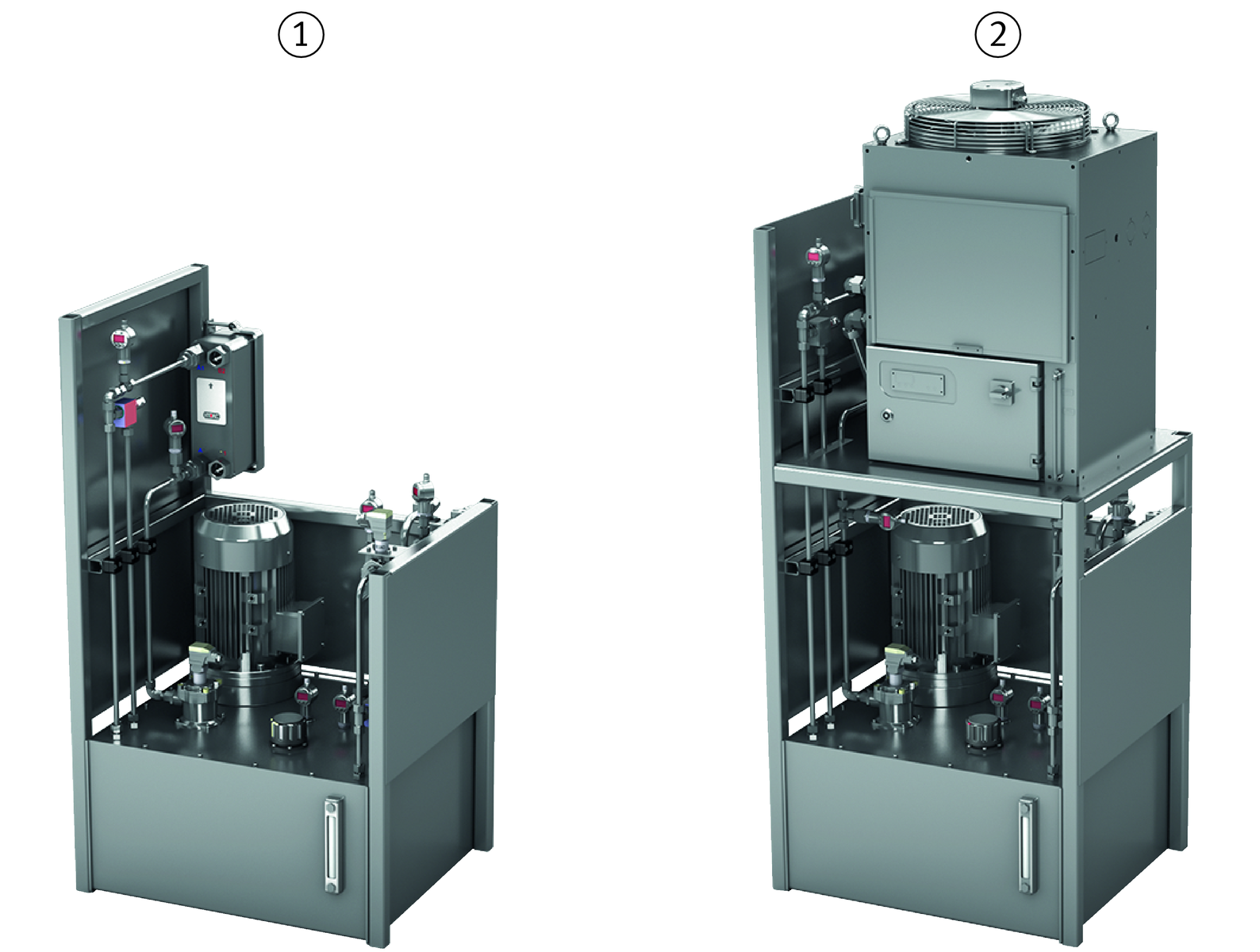
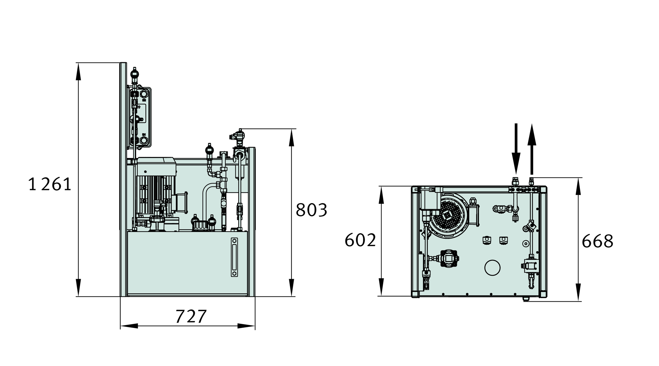
Dimensions
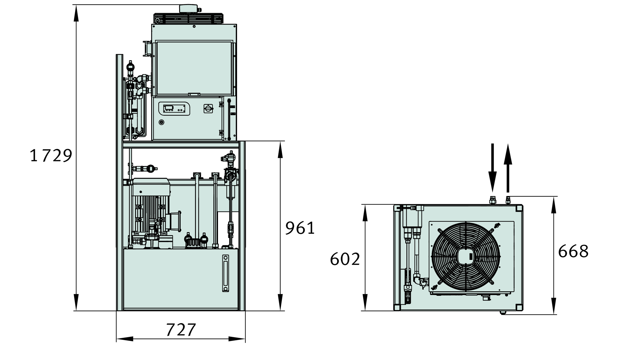
The external dimensions of the hydraulic units with and without a compressor cooling system differ only in the height, ➤ Figure and ➤ Figure.
Hydraulic unit for HLE45-A-XL without compressor cooling system
Hydraulic unit for HLE45-A-XL with compressor cooling system
The dimensioning of the hydraulic pipe connectors is dependent on the number of carriages for which the unit is designed, see table.
Hydraulic pipe connectors
Number of carriages | Hydraulic pipe connector | |
|---|---|---|
HLW45-A | Outlet | Inlet |
4 | 10L | 15L |
8 | 12L | 18L |
12 | 15L | 22L |
Extraction module (HYDAC)
The use of an extraction module, for example from HYDAC, gives significant advantages in oil extraction:
- Where there are long return distances to the hydraulic unit or when using energy chains, an additional extraction module is recommended in order to assist the return movement of oil. In order that the pressure on the extraction side of the carriage is as low as possible, the extraction module should be positioned as close as possible to the carriages. The extraction module is resistant to dynamic pressures in the outlet pipes and can compensate these dynamic pressures to a value of 2,5 bar.
- The use of an extraction module allows the use of significantly smaller hose diameters. This means that less space is required in the energy chain.
One extraction module can be used to extract from up to 4 carriages HLW45-A. Each extraction module requires an additional volume flow of 1,5 l/min.
Dimensions and hydraulic connections of the extraction module, ➤ Figure and table .
Extraction module
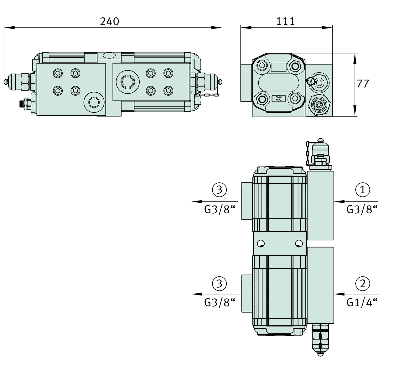
Hydraulic connections of the extraction module
Connector | Function | Recommended inside diameter of pipe |
|---|---|---|
mm | ||
Pump IN | Connector for the combined outlet pipes | 8 |
Motor IN | Supply of hydraulic oil to pump | 4 |
OUT | Connector for unpressurised outlet pipe | 16 |
Fluid diagram
Example unit with extraction module for demanding pipework systems
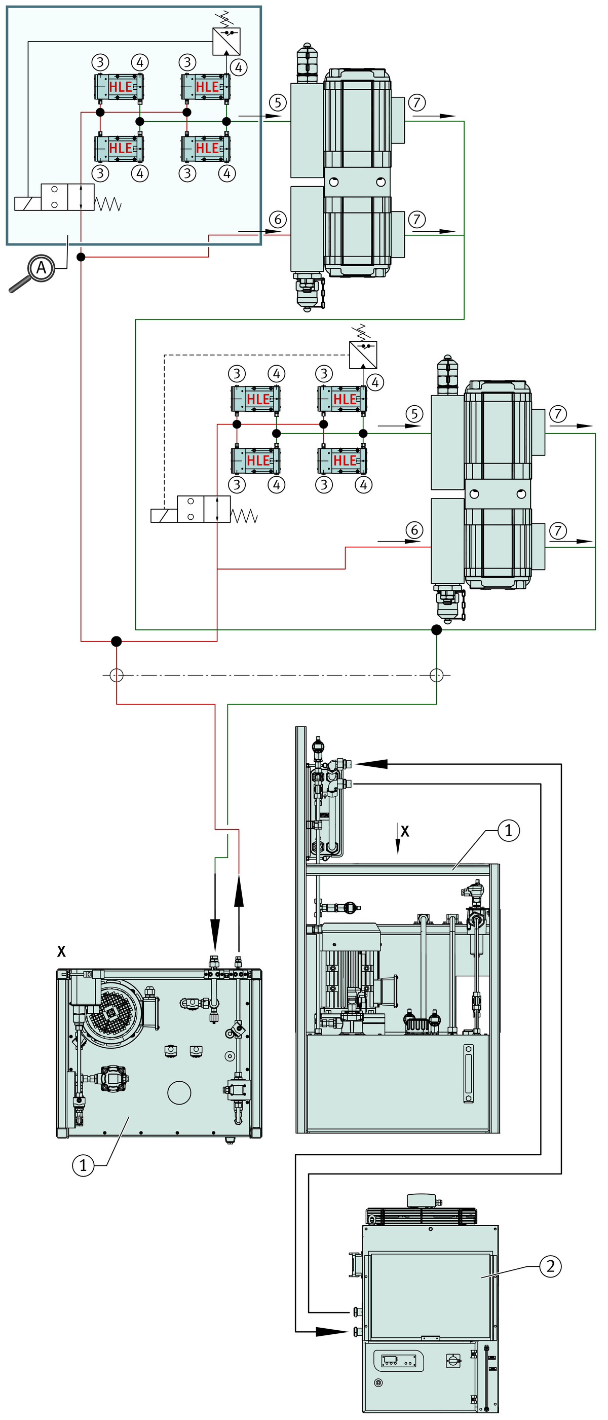


Example of safety circuit for protection against overpressure in outlet pipe
ACHTUNG
Pipe cross-sections should be designed in accordance with the volume flows.
Accuracy
Accuracy classes
The hydrostatic compact guidance system HLE45-A-XL is available in the accuracy class G1, ➤ Figure.
Parallelism tolerances of guideways
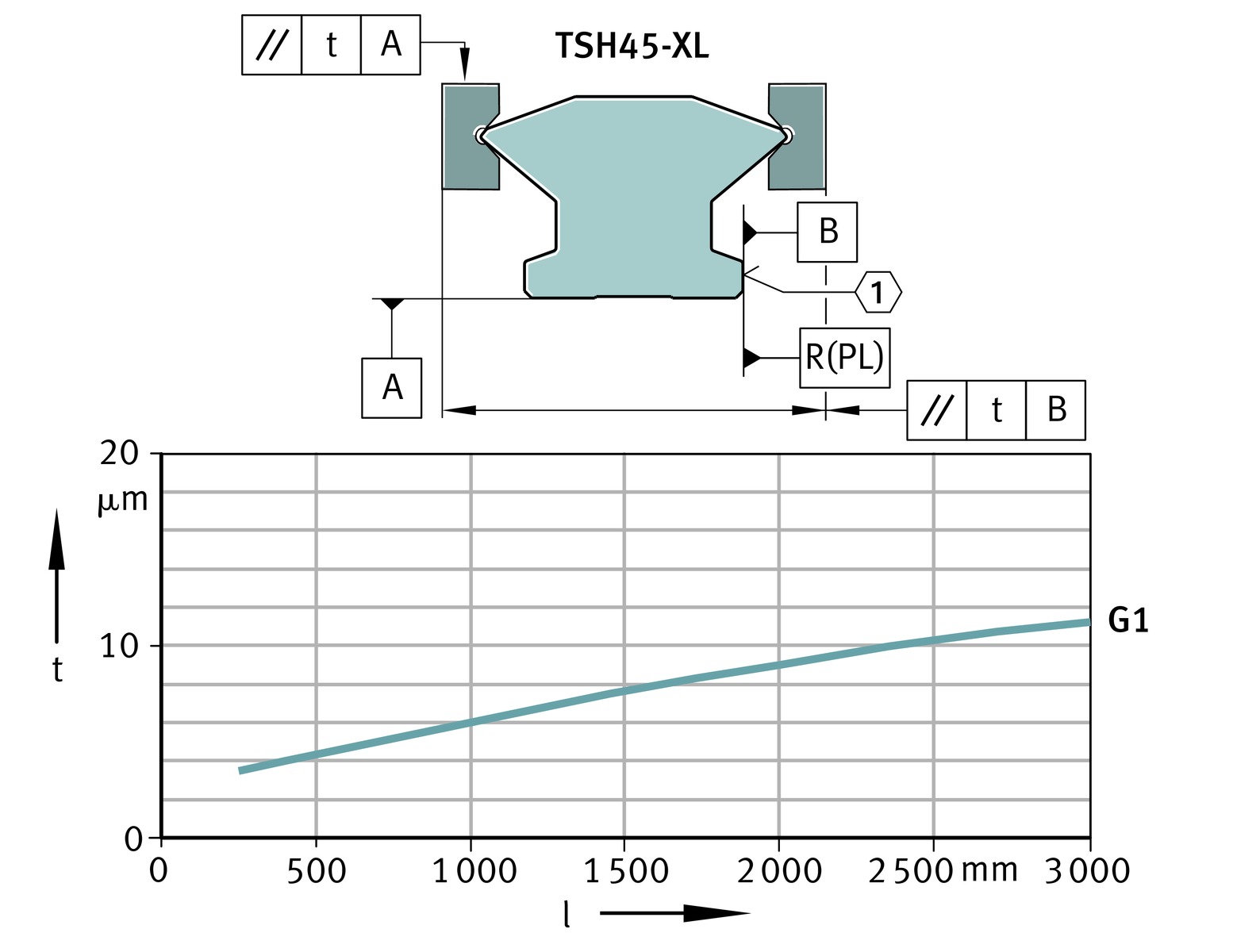
Parallelism of raceways to locating surfaces
The parallelism tolerance of the guideways is indicated for the accuracy class G1, ➤ Figure.
Tolerances
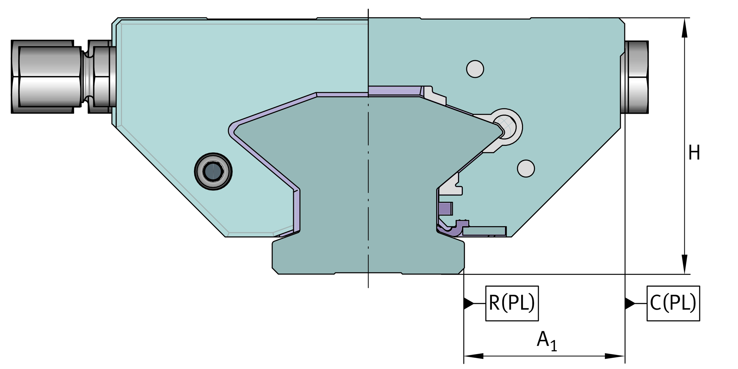
The tolerances are arithmetic mean values. They relate to the centre point of the screw mounting or locating surfaces of the carriage.
The dimensions H and A1 should always remain within the tolerance irrespective of the position of the carriage on the guideway, see table.
Datum dimensions H and A1, ➤ Figure .
Running accuracy
The running accuracy is influenced by the accuracy of the adjacent construction.
Tolerances of accuracy class
Tolerance | Accuracy G1 | |
|---|---|---|
μm | ||
Tolerance for height | H** | ±10 |
Difference in height** | ΔH | 5 |
Tolerance for spacing | A1** | ±10 |
Difference in spacing** | ΔA1 | 7 |
**Theoretical value used in production.
**Difference between several carriages on one guideway, measured on a calibration rail at the same point on the guideway.
Datum dimensions for accuracy
Positional and length tolerances of guideways
Positional and length tolerances of guideways, ➤ Figure and table.
Positional and length tolerances of guideways
Length tolerances of guideways
Designation | Tolerances of guideways, | |
|---|---|---|
≦1 000 mm | >1 000 mm | |
TSH45-XL | –1 mm | –1,5 mm |
** Length lmax .